Hi,
I'm currently doing some test to invert an audio signal with an amplitude up to 4Vpp using n-channel FETs only. From my simulations and practical tests, it looks like most inverting amplifiers with a gain of -1 are not working acceptable. I see lots of harmonics in the simulation and in practice, the same circuit is clipping. Does anybody have a hint what's the right way to invert a signal without additional or at least adding small gain but keep good THD?
Here is some input
https://sound-au.com/no-opamps.htm
but they already said, that it's not that good to do it like this. I thought it's a common issue but I don't find much information.
My supply voltage is 20V, single.
Many Thanks for any hint.
Q: Does anybody have a hint what's the right way to invert a signal without additional or at least adding small gain but keep good THD?
A: No way. Rules of thumb says, that in order to have low THD device must have high Gain.
To simply copy input to output using active device (G=+1) and keep -120dB THD, gain (capability - not current configuration) must be > 120dB. Inversion G=-1 doesn't play any role.
And if gain +60dB required, and THD < -120dB, than AOL must be > 180dB.
Thanks. At the moment I simulate a THD of about 60dB! 🙄 What do you think is the "best way" to invert the signal and minimize THD using JFETs?No way. Rules of thumb says, that in order to have low THD device must have high Gain.
To simply copy input to output using active device (G=+1) and keep -120dB THD, gain (capability - not current configuration) must be > 120dB. Inversion G=-1 doesn't play any role.
Lots of gain and negative feedback is the only way to get low THD from a very non-linear device like a FET... For high gain in one stage you need very high transconductance, which FETs don't really do... Basically the problem then becomes that of designing an opamp with only n-FETs. And as you'll need multiple stages stability will be an important challenge.
Or just buy a JFET opamp! It may not be all JFETs inside but it does the job and will have the the same low EMI susceptibility and high input impedance (and be smaller, cheaper, better).
For voltage amplification BJTs are so much more capable as you have high transconductance to build on.
Or just buy a JFET opamp! It may not be all JFETs inside but it does the job and will have the the same low EMI susceptibility and high input impedance (and be smaller, cheaper, better).
For voltage amplification BJTs are so much more capable as you have high transconductance to build on.
Thanks Mark. You know "The DIY design way is the aim!" and if there's no other way, an opamp will do the job perfectly. Leaving the signal inverted may also be fine for audio signals. But there are Fet circuits like the mu-amp that provides lots of gain. I'm thinking about a way using a feedback to provide unity gain. Maybe a modified differential stage may also allow the inverting signal.
But anyway, if there's no way doing it like that, I have to choose an alternative. At the moment I try to stay "pure JFET" without integrated circuits, but maybe this has some limits?
But anyway, if there's no way doing it like that, I have to choose an alternative. At the moment I try to stay "pure JFET" without integrated circuits, but maybe this has some limits?
With a bit of even-order distortion cancelling you might get acceptable results:I'm currently doing some test to invert an audio signal with an amplitude up to 4Vpp using n-channel FETs only. From my simulations and practical tests, it looks like most inverting amplifiers with a gain of -1 are not working acceptable. I see lots of harmonics in the simulation and in practice, the same circuit is clipping. Does anybody have a hint what's the right way to invert a signal without additional or at least adding small gain but keep good THD?
Circuit of course has zero PSRR but for large signal levels it should be OK with the typical supplies/regulators. Note the asymmetrical supply, though.
Matching of the FETs is critical, so best use some dual ;-)
Sim predicts THD below 0.01% @ 4Vpp, 1kHz
You can pick some ideas from :
www.diyaudio.com/community/threads/fet-based-phase-splitter.200325/post-2795781
www.diyaudio.com/community/threads/phase-inverting-not-inverting-preamplifier.192999/post-2658787
www.diyaudio.com/community/threads/necx-and-nesx-single-ended-to-balanced-converters.329767/
Patrick
www.diyaudio.com/community/threads/fet-based-phase-splitter.200325/post-2795781
www.diyaudio.com/community/threads/phase-inverting-not-inverting-preamplifier.192999/post-2658787
www.diyaudio.com/community/threads/necx-and-nesx-single-ended-to-balanced-converters.329767/
Patrick

If going with the distortion-cancelling scheme you may want to take a look at the JFE2140. It's a dual monolithic JFET so you will get good matching. Single JFETs won't perform as well in reality because their Gm varies a lot from device to device. Spice thinks all those devices are exactly the same so simulation results will be best-case, not worst-case.
The downside is that the JFE2140 comes in a very small SMT package.....
The downside is that the JFE2140 comes in a very small SMT package.....
Oh, this is really amazing, thank you @KSTR . I don't see the option of adding an offset voltage and this makes it ways better and with JFE2140 I simulate great results. Thank you!
Thanks @Mark'51 , Actually I'm using JFE2140 for my simulations and on the bench. SO8 is just about fine for me. ;-) Thanks for the hint.If going with the distortion-cancelling scheme you may want to take a look at the JFE2140.
Here's a slightly different way to do it. It also uses the JFE2140 but in a very different way. The resistor pair R3/R4 establish the gain. R4 sets the Gm of the buffer so the gain of the circuit is (about) -R3/R4.

This circuit's THD isn't quite as good as the previously-described approach. Its bandwidth is well above 1MHz.
You still want to AC-couple its output. Its output noise voltage performance sn't really all that great, considering the low-noise JFETs -- it sims out to around 9nv/sqrt-Hz.
The noise can be reduced by reducing the values of R3 and R4, but at the expense of higher distortion. When R3=R4 = 250 ohms the distortion rises to 1.7%, while the voltage noise is about 2.2nV/sqrt-Hz.
Apologies for the strange transistor symbols. They were created by the LTspice autoGenerator and I'm too lazy to make 'em "purty".
Thanks Mark. For me the performance is a little worse than #8. I have to add an offset because of my missing negative voltage and actually the gain isn't very accurate, but I will definitively check it in more detail within the next days. 👍
Apologies for the strange transistor symbols. They were created by the LTspice autoGenerator and I'm too lazy to make 'em "purty".
Don't worry about your "laziness". I'm familiar strange symbols. 😉
These are the results I got currently with your proposal, but as I said, I've just started thinking about it. Thanks again for the hint.
It just goes to show that there are many ways to skin a cat, so to speak 😀.
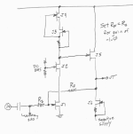
All-NJFET circuit with gain of -1.0 shown below.
J1 & J2 form a cascoded common source amplifier; output resistance is dramatically increased by the cascode device J2
J3 & J4 form a cascoded constant current source; output resistance is dramatically increased by the cascode device J4
J5 & J6 form a unity gain source follower (output buffer)
J1 & J2 form a cascoded common source amplifier; output resistance is dramatically increased by the cascode device J2
J3 & J4 form a cascoded constant current source; output resistance is dramatically increased by the cascode device J4
J5 & J6 form a unity gain source follower (output buffer)
Attachments
- Home
- Design & Build
- Electronic Design
- Unity gain inverting amplifier/buffer