I want to go fully balanced, ins and outs.If you want to go balanced ins, why not run a differential-input opamp then follow it with the rest of the circuit?
That does make sense, but based on some previous comments, I'm now more concerned the presence of the switch itself in the feedback network (and the wire routing to and from the switch) is in itself a source of noise and distortion.try running large value resistors, say a few megohms (value not critical) from the switch wiper to each select position.
You can have balanced ins going to single ended signal processing then balanced outs. Shucks, you don't even need to generate an opposite-phase output if you're running from the box to another balanced input; having the driven line (hot) and the opposite line tied to ground via the same impedance as present on the hot will balance the send properly with respect to the next stage.
It could be even simpler, I suppose. Transformers bookending a SE amp and be done. But this is not an exercise in economy or simplicity for me. I'm more curious to hear how active balanced will sound in this application.
If you want to go balanced ins, why not run a differential-input opamp then follow it with the rest of the circuit? Much simpler than two entire copies.
Are there any with JFET input, or at least with a very low input noise current?
I don't feel compelled to do any shaping beyond the standard curves.
Then make very sure the gap length of your playback head is short enough.
I know there are heads on the (professional) market that have physical gap lengths as large as 10 um. If there were no difference between physical and effective gap length, that would result in a sin(x)/x shaped response with a first notch at 38 kHz at 38 cm/s, but also with a drop to 2/π or about -3.52 dB at 19 kHz at 38 cm/s. In reality, it is somewhat worse because of edge effects (a.k.a. difference between physical and effective gap length). The frequencies scale with tape speed.
And change with wear of both heads and tape. If your goal is best possible reproduction, then you'll want to incorporate high frequency response trims, and you might need level trims (somewhere, preferably before metering if included). If your intended source tapes vary enough that you can hear the variation you might consider making the high frequency trim adjustable. At high enough impedances this could be done real time with air-variable capacitors. Member Wavebourn once suggested this for phono equalizers, crediting a friend whose name I have misplaced.
All good fortune,
Chris
All good fortune,
Chris
Understood, is this your concern due to frequency response, stability, other?
Rod Elliott is doing something similar in his design:
Per a lot of building/tweaking with similar tape pre circuits, I suggest you include some way to adjust the HF response for different PB head characteristics and suggest putting a 5 K pot in series with the C's for each EQ switch position. Pot also allows for HF tweaking as the head wears. Maybe have to reduce the C values ~10% to compensate. Also, the 68K, NAB value for R1x seems low. It "rolls off" the lows as a compromise for the LF boost and attempts to mitigate head bumps, but I've found that 100K is a better starting point. And depending on the head, you can get an additional HF rise above 10-15K - mitigated by lowering the value of R1L. Finally, do also suggest a cap around 100pf or higher across R1L.
Note: I measure frequency response with the benefit of having a Sound Technology 1500A. One of its great features for analog tape is to run/see a continuous 20 to 20Khz frequency sweep (in conjunction with its special alignment tape).
Finally, I haven't found any real benefit in having a balanced vs single ended circuit. Only problem I've encountered with single ended has to do with wiring out the head to the pre as cable lengths are much longer, I use a single conductor shielded cable from each head's channel to a pre connector AND in addition a single "ground" wire attached from as close as you can get to the PB head case to a signal ground on the pre. Just like is effectively done with all tone arms. Connect or don't use it as your situation warrants - can mitigate ground loops. And have FUN!


Is there a reason (aside from convenience) that the HF shaping needs to be done in the tape stage? Because another solution might be to just put a standalone equalizer between the tape and line preamps. In the interest of keeping the wires in the loop short (no panel pot) or having to open the enclosure to make adjustments.
Thanks, I'll give that a try.
I'm using a 5050 BIII, and based on my (limited and rudimentary) research, 47k seemed like the best input impedance. Basing that off what other pres designed for "medium to high inductance" heads have their out the box input impedance set to. What's your opinion on matching in my case?
This is for RF filtering I assume?
I get that, but I feel that on paper balanced makes sense given less gain per input signal. Even if it's just theoretical, maybe the feel good factor is enough for me.
Also, the 68K, NAB value for R1x seems low. It "rolls off" the lows as a compromise for the LF boost and attempts to mitigate head bumps, but I've found that 100K is a better starting point.
Thanks, I'll give that a try.
And depending on the head, you can get an additional HF rise above 10-15K - mitigated by lowering the value of R1L.
I'm using a 5050 BIII, and based on my (limited and rudimentary) research, 47k seemed like the best input impedance. Basing that off what other pres designed for "medium to high inductance" heads have their out the box input impedance set to. What's your opinion on matching in my case?
Finally, do also suggest a cap around 100pf or higher across R1L.
This is for RF filtering I assume?
Finally, I haven't found any real benefit in having a balanced vs single ended circuit.
I get that, but I feel that on paper balanced makes sense given less gain per input signal. Even if it's just theoretical, maybe the feel good factor is enough for me.
Is there a reason (aside from convenience) that the HF shaping needs to be done in the tape stage?
I can't think of any.
If the switch would only be used infrequently, consider putting it on the back panel of the unit, or internally, or directly on the PCB as DIP switches or jumpers.I was thinking that a 3 position non-shorting rotary switch would be alright. I could mitigate pop by connecting each switch position to a soft start relay that bridges the signal output to the terminals.
Then there is less risk of it being changed at the wrong time, by perhaps the wrong person.
Are there any with JFET input, or at least with a very low input noise current?
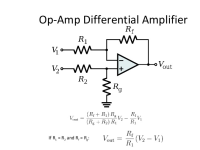
I meant a differential opamp circuit like this
(different image loaded because the one in the site is in the never-to-be-sufficiently-damned webp)
If you want to get fancy TI has at least one instrumentation amplifier which could fit the bill: https://www.ti.com/lit/ds/symlink/ina217.pdf
Attachments
The mute circuit for EQ switching, but it should be noted in advance that this is not a sophisticated or simple circuit, as the method uses the (time-uncertain) open state of the non-shorting switch in the middle of switching.
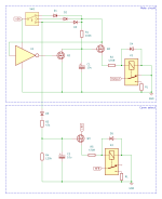
The power supply of the amplifier is ±18 V after stabilisation using the main transformer, so it is assumed to be the secondary winding of 18-0-18 AC.

The block in the bottom left of the circuit diagram (Ref 10x units) is a delayed mute circuit when the power supply is switched on and off; DIYers often omit such a circuit, but I am not impressed.
Q101 and R102 are constant current circuits that charge C102 when the power supply is switched on. When charged to approx. 5 V, Q102 and Q103 turn ON and the relay for muting unmutes the output (top left circuit).
When the power supply is switched off (or an unexpected power failure), R101 causes C102 to be quickly discharged as well, so the mute relay is quickly switched off and the outputs are muted.
The delay time for un-muting can be varied by the constant current value of Q101; 3 to 4 seconds is reasonable.
The constant current value of the FET is because the current flowing through it is very small, can be calculated using the following formula.
Id ≈ | pinch-off voltage |/R102
Second, the bottom right block (Ref 11x unit).
The moment the rotary switch for EQ switching is opened in the middle of switching, Q111 turns on, discharges C102 and turns off the mute relay, muting the output. The relay for EQ switching is slightly delayed by the C111-113 to ensure that it switches on (or off) after the outputs have been muted.
Resistors R106, 117, 121 and 125 in series with the relay should be adjusted so that the correct voltage is applied to the relay; 36 V relays are not often found in the standard range.
The 2SK117 is discontinued, but an equivalent SMD 2SK209 is available. Alternatively, almost any other variety with a pinch-off voltage of -2 to -0.3 V and a breakdown voltage of 35 V or higher can be used.
Similarly, BJTs can be used for general purposes type as long as Ic = 100mA or more.
The power supply of the amplifier is ±18 V after stabilisation using the main transformer, so it is assumed to be the secondary winding of 18-0-18 AC.
The block in the bottom left of the circuit diagram (Ref 10x units) is a delayed mute circuit when the power supply is switched on and off; DIYers often omit such a circuit, but I am not impressed.
Q101 and R102 are constant current circuits that charge C102 when the power supply is switched on. When charged to approx. 5 V, Q102 and Q103 turn ON and the relay for muting unmutes the output (top left circuit).
When the power supply is switched off (or an unexpected power failure), R101 causes C102 to be quickly discharged as well, so the mute relay is quickly switched off and the outputs are muted.
The delay time for un-muting can be varied by the constant current value of Q101; 3 to 4 seconds is reasonable.
The constant current value of the FET is because the current flowing through it is very small, can be calculated using the following formula.
Id ≈ | pinch-off voltage |/R102
Second, the bottom right block (Ref 11x unit).
The moment the rotary switch for EQ switching is opened in the middle of switching, Q111 turns on, discharges C102 and turns off the mute relay, muting the output. The relay for EQ switching is slightly delayed by the C111-113 to ensure that it switches on (or off) after the outputs have been muted.
Resistors R106, 117, 121 and 125 in series with the relay should be adjusted so that the correct voltage is applied to the relay; 36 V relays are not often found in the standard range.
The 2SK117 is discontinued, but an equivalent SMD 2SK209 is available. Alternatively, almost any other variety with a pinch-off voltage of -2 to -0.3 V and a breakdown voltage of 35 V or higher can be used.
Similarly, BJTs can be used for general purposes type as long as Ic = 100mA or more.
The diff-amp circuit of post #31 isn't appropriate for this use because it has conflicts between required input impedance and noise, but there are other ways to make a diff input, still with some (3dB) noise penalty, if really needed.
Switching at low signal levels in real time can be done quietly, but it requires that the switch contacts have zero/nada/nothing/nichts DC voltage across all contacts. If capacitors are involved it's best practice to bridge (appropriately large, so as to not be significant for signal) resistors across switch contacts, to enforce the no-DC rule despite some inevitable current leakage. Then choose switch contacts to be make-before-break or not, as appropriate.
To me, something continuously variable has its own attraction, but that's just a personal choice.
All good fortune,
Chris
@mason_f8 That's very impressive and bit over my head. I was thinking of doing something quite a bit simpler to avoid switches in the feedback network entirely.

Each EQ board connects to a switch position and all positions connect to mute circuit above. When powered on, C1 slowly charges and eventually reaches Q1 gate threshold voltage which switches on K2 and delivers signal to RL. While SW1 is between positions, K1 switches off, discharging C1 and switching off K2 immediately. D1 prevents energy stored in the coils from keeping the relays on. When the new switch position is reached, C1 has to slowly charge again. Instant off, delayed on.
Each EQ board connects to a switch position and all positions connect to mute circuit above. When powered on, C1 slowly charges and eventually reaches Q1 gate threshold voltage which switches on K2 and delivers signal to RL. While SW1 is between positions, K1 switches off, discharging C1 and switching off K2 immediately. D1 prevents energy stored in the coils from keeping the relays on. When the new switch position is reached, C1 has to slowly charge again. Instant off, delayed on.
I could also use the above muting circuit and instead of each switch position controlling power to a board, use reed relays to switch the feedback network in a single board. I'm guessing that relays in feedback path, like your design, wouldn't be nearly as noisy as a regular mechanical switch?
#34 circuit, but the relay takes a little time for the contacts to return after the applied voltage of the solenoid is removed. There is concern that if the changeover switch is turned quickly, the K1 contacts may not switch back.
Also, the energy stored in the relay's solenoid is generated as a back-voltage after the applied voltage is removed, so a diode must be connected directly to the solenoid in parallel.
As Q1 is a source follower, K2 may not have sufficient voltage.
I have not experienced any particular noise concerns with relays. However, the current of the solenoid that turns on and off should not flow directly to the GND of the signal system.
In terms of circuit stability, the NFB network path should be routed as close to the OP-AMP as possible and as short as possible, so you must keep in mind that the wiring to the relay should be short, but this is more advantageous than routing the feedback path to the switch located on the panel.
Last edited:
Thanks for pointing that out, I hadn't considered that.#34 circuit, but the relay takes a little time for the contacts to return after the applied voltage of the solenoid is removed. There is concern that if the changeover switch is turned quickly, the K1 contacts may not switch back.
This is true, I could increase the control voltage if it doesn't work on the breadboard.As Q1 is a source follower, K2 may not have sufficient voltage.
Here's another attempt using complementary mosfets to control the discharge instead of a relay.
That's a relief and will save a lot on parts.I have not experienced any particular noise concerns with relays.
Makes sense, I'll prioritize that proximity when laying out the PCB. I'm thinking of using differential reed relays for each curve, hot and cold being switched in the same relay.In terms of circuit stability, the NFB network path should be routed as close to the OP-AMP as possible and as short as possible, so you must keep in mind that the wiring to the relay should be short, but this is more advantageous than routing the feedback path to the switch located on the panel.
The polarity of D1 seems wrong.
If Q1 and Q2 are fairly low on resistance MOSFETs and Q2 has a substantially lower threshold voltage than Q4, you might get a nasty overlap current bump after SW1 opens:
First, Q4, R2 and K1 pull down the gates of Q1 and Q2 well, so everything works as intended and Q3 turns on, gradually discharging C1.
As the voltage across C1 gets close to the threshold voltage of Q4, Q4's on resistance increases. When it becomes >> 100 kohm, the voltage at the gates of Q1 and Q2 starts to track the voltage across C1.
If Q2 has about the same threshold voltage as Q4 or higher, it will hardly conduct, like Q4. Only if Q2's threshold voltage is hundreds of millivolts less than Q4's, it might draw a substantial overlap current.
Possible solutions: the use of a small CMOS inverter for Q1 and Q2, a series resistor somewhere, using a Q2 that has at least as high a threshold voltage as Q4.
@MarcelvdG Thanks for that, I'll try a CMOS inverter.
Also spent a little time playing around with a delayed on/off for the feedback network.

Each switch position connects to a curve select circuit. When switched, the mute circuit will disconnect output immediately, and the last position's curve select will disconnect after a short delay. The new curve select will connect after a long delay, and the mute circuit will reconnect output after a longer delay.
Also spent a little time playing around with a delayed on/off for the feedback network.
Each switch position connects to a curve select circuit. When switched, the mute circuit will disconnect output immediately, and the last position's curve select will disconnect after a short delay. The new curve select will connect after a long delay, and the mute circuit will reconnect output after a longer delay.
Last edited:
- Home
- Source & Line
- Analogue Source
- Tape Head Preamp