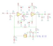
Working on a tape head preamp for open reel with selectable EQ for NAB and CCIR curves. This is based on the reference application on the LT1115 datasheet and Rod Elliott's Project 247. This is really a stab in the dark so feedback would be greatly appreciated.
Attachments
Moving the EQ switch with the volume turned up could be very bad for the amplifier and speakers,
especially if you use a non-shorting switch.
C11 should be more like 10uF NP unless your line stage has at least 100k input impedance.
especially if you use a non-shorting switch.
C11 should be more like 10uF NP unless your line stage has at least 100k input impedance.

Some great practical advice, thank you. When the switch is shorted, the feedback path becomes the resistor network for HF roll off applied to all frequencies, right? That seems like a good thing to me, so I'm obviously missing something fundamental here, sorry.Moving the EQ switch with the volume turned up could be very bad for the amplifier and speakers,
especially if you use a non-shorting switch.
Great note, I'll bump that value.C11 should be more like 10uF NP unless your line stage has at least 100k input impedance.
The switch could pick-up a lot of hum. Wouldn't it be better to redesign the FB network and place the switch at the pre output end of it?
Does that mean after the opamp, do eq in feedback path, then another opamp for gain, then buffer?
In the case of playback-only HEADs, the winding impedance is high in order to obtain a high output from minute tape magnetic changes. In such cases, a low-voltage noise OP-AMP like the LT1115 may not be the best choice due to high current noise; with J-FET inputs, current noise is negligible, so it is recommended to consider a low-voltage noise one among them.
Does that mean after the opamp, do eq in feedback path, then another opamp for gain, then buffer?
It would be better to not switch the EQ at all and hard wire it, if you will only use one of them anyway.
I would like the option to play both older consumer tapes recorded at NAB and IEC 7.5, as well as newer master copy tapes at IEC 15.
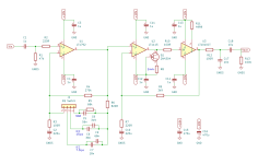
The EQ-network is a load for the op-amp.Here's an updated schematic. I put the EQ and switch in the LT1792 loop, use the LT1115 for voltage gain, and LT1010 for buffer.
BTW, did you simulated the pre? A Bode-plot (gain AND phase vs frequency) would be benefical.
The EQ-network is a load for the op-amp.
Understood, is this your concern due to frequency response, stability, other?
Rod Elliott is doing something similar in his design:

It would be better to not switch the EQ at all and hard wire it, if you will only use one of them anyway.
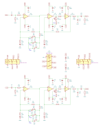
I'm trying to figure out some ways to mitigate this issue. One option would just to have 3 complete signal paths (12 actually for balanced stereo) in one box and instead of switching EQ curves I just switch cables... but that is a bit inconvenient. Or single pair of inputs and outputs on case which gets split internally to 3 paths, the EQ switch actually selects which amp receives power.
Thinking this through more, for the dedicated signal path with multiple boards to work, I assumed I'd need to control everything via centertapped relays so that power, input, and output are all switched. Complicates things a bit but isolates all paths so that inactivate states don't influence the active path.
Does this mean using three of these circuits, one for each equaliser separately?
That seems very wasteful.
By the way, have you decided which type of switch to use for switching equalisers?
Is it a rotary switch with three contacts? Is it a short type or a non-short type?
That seems very wasteful.
By the way, have you decided which type of switch to use for switching equalisers?
Is it a rotary switch with three contacts? Is it a short type or a non-short type?
mason_f8 said:Does this mean using three of these circuits, one for each equaliser separately?
That seems very wasteful.
I agree, but I'm not smart or experienced enough to find a solution that doesn't compromise sound quality. And this is only one channel, so I'll need six of these in the enclosure for stereo.
mason_f8 said:By the way, have you decided which type of switch to use for switching equalisers?
Is it a rotary switch with three contacts? Is it a short type or a non-short type?
I was thinking that a 3 position non-shorting rotary switch would be alright. I could mitigate pop by connecting each switch position to a soft start relay that bridges the signal output to the terminals.
When I created a phono equaliser amp before, I included a circuit to mute the shock noise when switching between MM and MC. I'll see if I can apply that circuit, give me a few days.
If you want to go balanced ins, why not run a differential-input opamp then follow it with the rest of the circuit? Much simpler than two entire copies.
Also, a trick I saw from a pro-sound EQ: try running large value resistors, say a few megohms (value not critical) from the switch wiper to each select position. That will keep the otherwise open end of the EQ capacitors at the same DC voltage as the opamp negative input and eliminate pops when switching.
Also, a trick I saw from a pro-sound EQ: try running large value resistors, say a few megohms (value not critical) from the switch wiper to each select position. That will keep the otherwise open end of the EQ capacitors at the same DC voltage as the opamp negative input and eliminate pops when switching.
- Home
- Source & Line
- Analogue Source
- Tape Head Preamp