Thank you for your clarification @hifiamps . Currently, my TDA1541 uses D1Pass as I/U conversion, so I wonder what can be achieved by including the C-3850 between D1Pass and the amplifier? Will this affect the quality and tone of the sound in any way? How then to set the gain of the C-3850? Will this reverse polarity issue have any negative impact?
I would not do that. You can use either the Pass D1 active I/V or passive I/V with the C-3850 as described above. Compare the two, and see which one you like. The quality of the I/V resistor in passive I/V makes a big difference in terms of sound quality. Once you determine the proper value, and if you like the sound quality in general, you can improve it further by using TX2575 metal foil (Vishay Z-foil), (possibly SMD tantalum nitride), or Caddock TF020 thick film resistors.

Hi, I'm planning a build of one of these, but am new to this kind of thing and am not sure how big a transformer i need. I know its a 15-0-15 but does anyone know what wattage i could get away with? Thanks for any help.
https://www.aliexpress.com/item/100...7xnqekf2&utparam-url=scene:search|query_from:
https://www.aliexpress.com/item/100...7xnqekf2&utparam-url=scene:search|query_from:
Attachments
30VA should be efficient because we have about 100mA current at the mod version at each rail.
kr
chris
kr
chris
Yes 30 VA are too much.
But
VA is Not Watt
From 15 Volt secondary we get after rectifier 21 volts. This is going to each rail to a voltages Regulator 7815.. etc.
So we have about 2.1 Watt per rail consumption. So overall about 4.2 Watt ....round 5 Watt. So we have bad efficiency of the transformer... can calculated the double. So 10 VA must be fine.
Kr Chris
Really like this project. Starting on my second board with @chalky mods. So, just need to clarify the direction of the diode since I'm a newbie. Easiest is to post two pictures.They have a cathode ring mark, which connects to the negative voltage potential. The opposite lead (anode) connects to the positive voltage.
grateful if someone can confirm if this will be right or wrong
That orientation is correct. E-352 is the part number, 3.50mA. They should be selected in matched pairs. The data sheet also has a table "How to compensate current reduction due to heat up of the CRD. For currents of 1 mA or more, resistors can be used together with CRDs to compensate for current decreases and fluctuations. The following values are typical for compensation resistors." For the E-352 it lists an 82K resistor. The resistor is placed in parallel with the CRD.
@chalky mods in Post #177 .
@chalky mods in Post #177 .
Last edited:
Thanks. Would you recommend a 82k in parallel in this application? According to the data sheet it doesn’t hurt to ad one.
I have no personal experience with CRDs with or without the resistor. "Compensate for current decreases and fluctuations" sounds like a good thing. Try with and without?
I recently finished a balanced version of chinese C-3850's, I followed chalky's mods but used 5.1k resistors instead of CRD's. Very pleased with the sound.
Good Morning,
I'Nicola and writing from Italy. Yesterday arrived me this kit clone c3850
https://www.ebay.it/itm/40515565463...6&customid=smRmcUUjAAAAlZhhceybF3Iz9XBCAAAAAA
can You make a quick summary of the minimum changes needed?
thank you and sorry me for my terrible english.
thank You so much
nicola
I'Nicola and writing from Italy. Yesterday arrived me this kit clone c3850
https://www.ebay.it/itm/40515565463...6&customid=smRmcUUjAAAAlZhhceybF3Iz9XBCAAAAAA
can You make a quick summary of the minimum changes needed?
thank you and sorry me for my terrible english.
thank You so much
nicola
Hi nicola
please read some page and dicide what changes are you want to make and able to do.
kr
chris
please read some page and dicide what changes are you want to make and able to do.
kr
chris
Hi NicolaiGood Morning,
I'Nicola and writing from Italy. Yesterday arrived me this kit clone c3850
https://www.ebay.it/itm/40515565463...6&customid=smRmcUUjAAAAlZhhceybF3Iz9XBCAAAAAA
can You make a quick summary of the minimum changes needed?
thank you and sorry me for my terrible english.
thank You so much
nicola
My inspiration was Michael Beenys channel on YouTube
My first board is based on his recommendation. Recommended you to check out his video.
Per
I have finally tried this preamp. Needed 15dB gain. It sounds very nice with the original circuit. Just starting from the power supply. The usual recommended output caps in the datasheet for the L7815 is 0.1uF and L7915 is 1uF. These are for optimal transient response. Music requires transient response. The circuit uses 100uF, which seems way too high. Has anyone tried 0.1uF and 1uF in place of the 100uF?
Just an opinion, but I would skip the onboard PSU and 'pipe-in' your own DC supply rails. Using a separate power supply will cost more money and effort, but you can skip those components on the C-3850 PCB. In my view, it does not cost much more, really, but it can be considered trivial or diminishing returns with such a circuit.Just starting from the power supply.
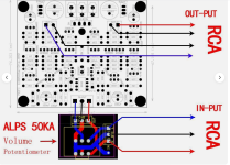
Here is a pic with some landmarks on it. Could be handy when using the Chalky Schematic?
Cheers
Attachments
Last edited:
- Home
- Amplifiers
- Solid State
- Clon C-3850