PS Please use English. Some of us are fluent in Russian, but not everyone.
I apologize - it's not on purpose
I try - but sometimes Chrome automatically translates the page - and I forget to check it

JJ KT77 25 Watt, 10500 gm, 180 mA max DC $28
21LG6A 28 Watt, 11500 gm, 315 mA max DC $4
I wonder - how much do GU50 and 6P45S (6P42S) really cost?
A well supported kit, with many builders, PCB based can be a godsend.
but what about "old school" - surface mounting?🙂
and you don't need a board - and soldering is a pleasure🙂
The OT, PWR Xfmr and case are where the $$ is.
In PP on 6п41с - work great as an output transformer - toroidal transformers - no need to overpay for a "big name"
I have made something similar in a push pull amp. I used mosfets for the G2 buffer.
This scheme of yours is not a secret?
Then there are others with more experience, or pretty adventurous, where they think about starting with an 845 SE with 1200V B+. For those the sky is the limit, and are ready to experiment with everything.
I don't believe it 🙂)
Attachments

I personally prefer point to point wiring, but I'm one of the "old school” ones, in the same way I prefer manual gearboxes in cars.but what about "old school" - surface mounting?
PCB makes it easier for new builders. That's a fact, regardless of how enjoyable point to point wiring may be.
Good GU-50/LS-50 sockets are not cheap. The tubes are cheap as chips though.I wonder - how much do GU50 and 6P45S (6P42S) really cost?
The 6P41S/6N41C and 21LG6A are both TV Sweep type tubes, which usually can be up-rated by 33% for audio usage due to audio signal statistics.
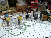
Old fashioned spring clip point to point wiring without soldering:

Old fashioned spring clip point to point wiring without soldering:
Not a secret, but I can't find the diagram. It's posted on here somewhere.This scheme of yours is not a secret?
Look at the circuits in this thread. Where there is a triode used to drive G2, I used an N-ch mosfet. It's a follower, so Gm is the most important parameter and a mosfet beats any vacuum tube in Gm. My circuit was similar to the one in post #12 except for the mosfet in place of the 6SN7. It is possible to get the drain voltage the plate supply when using a TV sweep tube that runs 150 to 200 volts on the screen. The 200 volt "B2" supply can be a pot from B+ to ground since there is little current flow. If a KT88 or similar tube is used then some tricks will be needed to keep the screen voltage from going flat when screen needs more voltage than the B+ supply has. Here a pair of diodes feeds the drain, one is connected to B= the other is connected to the plate so the screen current is stolen from the plate of the tube.
I was looking for examples of EL86 amplifiers, and have come across this interesting candidate.
It is credited to a person called 'lagarto', and is partially described here ...
EL86SE
It has the whiff of Japanese innovation about it, and I'm sure it could work, but could it match a transformer with a UL tap?
If it is an effective alternative, then there are lots of tubes with lower voltage rated screens that could surely benefit from this approach?
It looks deceptively simple. What are the purposes of the 100uF from the primary of the OPT to the EL86 cathode? And the 47R?
- OldHector
- Replies: 38
- Forum: Tubes / Valves
Not a secret, but I can't find the diagram. It's posted on here somewhere.
good work from a creative point of view
and what is the real result?
for example - spectrum distortion at 5 watts of power?
how much is the IMD and TND?
The universal driver board evolved from that schematic which was created by playing with a bunch of parts on my old vacuum tube breadboarding system, the TubeLab III back in 2009. The intended use at that time was for screen driving a medium sizedThe Universal PP Driver on your web page?
TV sweep tube. Some of the early work was detailed scattered throughout this old thread, starting in post #94. This was an exercise in development of an amplifier on two different continents when I was working 60 hour weeks and had no time to test any ideas.
In this thread Amp design suggestions Eli was suggesting a 6L6 AB2 design based on Mullard 5-20 topology with 12AT7 front end and ECC99 LTP and Mosfet source followers. Respecting the original thread, Eli asked to start this new one.
I am interested in progressing with this design, looking for any assistance 😉
Cheers,
Chris
I am interested in progressing with this design, looking for any assistance 😉
Cheers,
Chris
- chrish
- Replies: 689
- Forum: Tubes / Valves
The final version is detailed in this thread:
The Universal Driver Board (UDB) was a concept that was underway in 2009 when the 6L6GC in AB2 thread appeared. The design concepts are discussed throughout that long thread. The circuit features two cascaded LTP's made from dual triode tubes. I have made several different versions of a similar design with 9 pin miniature, and octal tubes. The Octal version was used for Chrish's amp design, and for my test breadboard. Several different types of output tubes have been tested through my breadboard. The thread is here...
- Tubelab_com
- Replies: 414
- Forum: Tubelab
Attachments

The experiment to run a tube in simulated UL from a transformer without UL taps was done 12 to 15 years ago. I posted my experiment on this forum somewhere, but I could not find it with the search engine yesterday. I usually take the easy measurements on most of my experiments, so the THD vs Power data exists somewhere. IMD pictures were often done, but I lack the notch filter for taking accurate numeric data.good work from a creative point of view
and what is the real result?
for example - spectrum distortion at 5 watts of power?
how much is the IMD and TND?
When my 41 year engineering career ended abruptly in 2014, I sold my house in Florida and moved everything that I wanted to keep 1200 miles north. What was planned to be an organized exit over several months turned into a hectic panic because I had 3 weeks to get out of my house. I had friends and neighbors helping load stuff into moving trucks and PODS. My stuff was stored in whatever space I could find or rent for almost two years while my new house was being built. Now, over 10 years later I realize that a lot of "stuff" was lost. Two large boxes of paper notes and log books were gone along with a few pieces of test equipment, and lots of small stuff. The white "Lego Block" TubeLab III breadboarding base is here, but all of the blocks (the drop in modules) are missing. New ones are being made now.
I just found some triode curves of 6P41S someone measured and they ARE very impressive, at least for above 10 mA:
Better than the datasheet shows.

Better than the datasheet shows.
I just found some triode curves of 6P41S someone measured and they ARE very impressive, at least for above 10 mA:
Better than the datasheet shows.
https://www.diyaudio.com/community/attachments/vasilich-6n9s-6p41s-jpg.1402764/
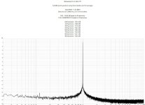
If you make this circuit and tune it with a spectroanalyzer, you will forget triode circuits with their “heavy” driver stages, low power and high NIR.
In this circuit it is realistic to get 0,08% THD at 4-5 watts with a feedback depth of 4 dB.
And this is in Class A !!!
Maximum power - 20 watts !!!
why to make 5 triodes in the input stage to get 7 watts at the output with TND 3%????
look at the “icon” of tube sound - 300b - is it written in the passport - 4,5% THD ?
or did humanoids from Mars mistakenly print 4.5% THD?
Translated with DeepL.com (free version)
https://frank.pocnet.net/sheets/084/3/300B.pdf
Modern 300b manufacturers do not specify the level of TND - and why ?
- Home
- Amplifiers
- Tubes / Valves
- What tube amp to build