Она хороша. Просто не так хороша, как LM317
most likely - the opposite.
but this relates to the potential of the scheme, but does not relate to your opinion regarding "what is better" and "what is worse"
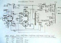
например, вот базовая схема
https://www.nadotornado.com.ua/media/kunena/attachments/62/6П3С_.JPG
По моему скромному мнению, нет необходимости в дополнительных стабилизированных источниках питания постоянного тока, экранных сеток, включая диоды Ценнера.
you can simply do it as in the diagram and listen
or you can do it this way:
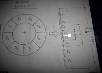
1. output transformer - TOR
on top of the primary and secondary windings - 10-20-30 turns of an additional secondary winding
and here - we connect the load to the assembled amplifier - first without an additional secondary winding
we fix the THD at a power of 5 watts - 0.45%
further - add 5 turns from the additional winding to the secondary winding - measure - 0,41%
further - add 5 more turns from the additional winding to the secondary winding - measure - 0,37%.
etc...
is this the filigree tuning of a tube amplifier.
or you can change the supply voltages of the second grid - and thus achieve exact matching of the output transformer with the load.
BUT!
damping the extra voltage of the second grid supply with a resistor is evil!
That's where you need a stable resistor in series.
check it yourself🙂
choke is a must!!!!!
GU50 (500 В/250 В)
очень неблагоприятный режим
этой лампе нужны 540 и 280
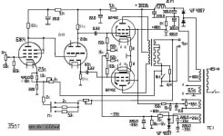
Этот блок питания идеально подходит для выходных ламп строчной развертки телевизоров с ЭЛТ.
6П41С,
6П36С, ЭЛ500
6П45С, ЭЛ509
Вместо двух первых электронных ламп в схеме можно использовать одну лампу 6SL7 .
https://forumimage.ru/show/112174653
Attachments
Last edited:
не так хороша, как LM317
Stabilizing one power supply and leaving the rest of the amplifier circuitry unstabilized is obviously a very bad idea.
For example.
You set up an amplifier with these input parameters
- 400 volts anode
- 300 volts second grid
- 6.3 volts high.
Everything seems to be perfect.
BUT!
At volume peaks, the anode voltage will drop (yes - by a small amount of volts - but there will be a drop).
Likewise, the filament supply voltage will also sag.
And only a stabilized second grid will keep a constant voltage - no matter how much the anode and filament power supply sags.
Have you looked with a spectrum analyzer ? What parameters your amplifier gives out at 394 anode and 6.25 filament?
The conclusion is simple: lm317 is a very very very very good plastic chip, which should be used where it is needed.
And if there is a desire that the power supply of the amplifier was stable - it makes sense to be concerned and buy a network voltage stabilizer - then all the supply circuits of the lamps will be fed "in unison"
If you stabilize only one second grid - it is almost 100% "cacophony".
"If you stabilize only one second grid - it is almost 100% "cacophony"."
My own amplifiers using the LM317 regulator for the screen grids have extremely low distortion. They certainly do not sound cacophonous. This notion is completely incorrect. See the schematic of the "Grommes Hi-Fidelity Model 260 A". Note the 6L6GB regulator on the screens. Yes, it is a very rudimentary voltage regulator. The LM317, with a much more sophisticated error correction amplifier, works much better. It also works great with TV horizontal deflection tubes, which have much lower screen voltage ratings than plate ratings. The Maida type regulator is very inexpensive to build and works incredibly well. Just try it for yourself. It's also a nice safety device to drain the B+ caps. An all around winner.

My own amplifiers using the LM317 regulator for the screen grids have extremely low distortion. They certainly do not sound cacophonous. This notion is completely incorrect. See the schematic of the "Grommes Hi-Fidelity Model 260 A". Note the 6L6GB regulator on the screens. Yes, it is a very rudimentary voltage regulator. The LM317, with a much more sophisticated error correction amplifier, works much better. It also works great with TV horizontal deflection tubes, which have much lower screen voltage ratings than plate ratings. The Maida type regulator is very inexpensive to build and works incredibly well. Just try it for yourself. It's also a nice safety device to drain the B+ caps. An all around winner.
Last edited:
Они определенно не звучат какофонично.
They certainly do not sound cacophonous.
not only everyone knows about it!
Probably - you are the leader of tube amplifier craftsmanship in a niche where you can't do anything without a plastic chip.
But life goes on.
And schemes where one voltage is stabilized and other voltages are not stabilized also have the right to exist.
Of course, I am fundamentally wrong, because I understand why you should not use stabilization of the second grid without stabilization of anode voltage and filament.
But with a master in the niche of tube amplifiers with stabilization of the second grid power supply in isolation from stabilization of the rest of the tube power supply circuits - there is certainly no point in arguing with me.
It is so very simple. Just do it. You have not done it, so you don't know the result. You will never know the result until you actually do it. It's 2025. Stop living in the past. Enhance the best aspects of tubes with solid state devices.
Grommes 260A engineer A.A. Hart would have been stunned if he had access to a LM317.
Grommes 260A engineer A.A. Hart would have been stunned if he had access to a LM317.
Перестаньте жить прошлым
stop living in parallel spaces
it's winter outside
and you're talking about a plastic microcircuit
cacophony is not a death sentence
LM317 is an excellent plastic microcircuit
I'm with SY on this one. 2005. Get with the times. https://www.diyaudio.com/community/threads/pp-pentode-screen-supply.49466/post-561634
Tubelab_com https://www.diyaudio.com/community/threads/screen-grid-resistors.71665/post-815483
Tubelab_com https://www.diyaudio.com/community/threads/screen-grid-resistors.71665/post-815483
Last edited:
Here's another thread: https://www.diyaudio.com/community/threads/6bq5-screen-voltage-regulator.182032/
How about ChatGPT:
A voltage-regulated screen grid pentode is a specific type of pentode vacuum tube in which the screen grid (G2) voltage is regulated or controlled to remain at a constant value, regardless of fluctuations in the anode voltage or other circuit conditions. This regulation improves the stability and performance of the tube, especially in circuits where high linearity, low distortion, and efficient operation are critical.
Basics of a Pentode
To understand the voltage-regulated screen grid pentode, let’s first look at the basics of a pentode tube. A pentode has five key components:- Cathode (K): The heated filament that emits electrons when heated.
- Anode (Plate, A): The electrode that attracts electrons, creating a current.
- Control Grid (G1): Controls the flow of electrons between the cathode and anode by applying a negative voltage, influencing the tube's output.
- Screen Grid (G2): Positioned between the control grid and the anode, the screen grid helps to accelerate the electrons toward the anode and shields the control grid from the anode’s influence. Its voltage is critical for the efficiency and linearity of the pentode.
- Suppressor Grid (G3): Minimizes the emission of secondary electrons from the anode that could otherwise return to the anode, thereby improving efficiency.
The Problem with Unregulated Screen Grids
In a traditional pentode (without regulation), the screen grid (G2) is often connected directly to the power supply or a fixed voltage source. However, the voltage at the screen grid can fluctuate for several reasons:- Power supply instability: If the power supply is not perfectly stable, it can cause variations in the screen grid voltage.
- Anode voltage fluctuations: Variations in the anode voltage can also cause fluctuations in the screen grid voltage, especially in circuits with complex loads or varying currents.
- Distortion: Unregulated screen grid voltage can cause nonlinearities in the tube's amplification, leading to distortion in audio applications.
- Efficiency problems: Fluctuations in the screen voltage can cause less efficient operation, reducing the tube’s performance in high-demand applications.
Voltage-Regulated Screen Grid Pentode
In a voltage-regulated screen grid pentode, the screen grid (G2) is controlled by a voltage regulator that keeps its voltage stable. The regulator typically uses a feedback loop to monitor and adjust the screen grid voltage to ensure that it remains constant even when other parts of the circuit (like the anode voltage or power supply) fluctuate. The regulation is typically done by shunt or series regulators that adjust the voltage to a specific value based on a reference or desired operating condition.Key Features and Benefits
- Improved Stability: By maintaining a constant screen grid voltage, the tube operates more stably, reducing the effects of voltage fluctuations from the power supply or load changes.
- Reduced Distortion: Voltage regulation helps maintain linearity in the tube's response, which results in lower distortion, particularly important in high-fidelity audio amplifiers.
- Higher Efficiency: With a stable screen grid voltage, the pentode operates more efficiently, especially under varying operating conditions.
- Better Performance in Complex Circuits: Voltage-regulated screen grid pentodes are particularly useful in circuits with variable load conditions, such as power amplifiers, where maintaining consistent performance is critical.
- Longevity and Reliability: The regulated voltage helps prevent excessive stress on the tube, improving its lifespan and reliability.
Applications
Voltage-regulated screen grid pentodes are used in situations where:- High performance is essential, such as in audio amplifiers (especially high-end or tube-based audio equipment).
- Stable operation is required over a wide range of operating conditions, such as in RF (radio frequency) amplifiers or other power amplifiers.
- Precision electronics demand low distortion and efficient amplification.
Example
An example of a voltage-regulated screen grid pentode might include tubes used in high-fidelity (hi-fi) audio amplifiers, where audio clarity and stability are paramount. The regulation of the screen grid ensures that any fluctuations in the power supply or other components do not affect the performance, resulting in cleaner sound output with minimal distortion.Conclusion
In essence, a voltage-regulated screen grid pentode is an advancement over a traditional pentode, incorporating regulation of the screen grid voltage to maintain consistent performance, reduce distortion, and improve efficiency, especially in high-demand applications. It is most valuable in scenarios where stability and high-quality signal amplification are critical, such as in professional audio equipment or complex high-power amplifiers.A reference article. See Section 5:
The Screen Grid therefore, when connected for tetrode, pentode or beam power tube operation, should always be supplied by a suitable low voltage direct current supply, having a low-impedance path to ground - ie effectively AC earthed.
The screen-grid supply should be regulated - or have good regulation properties - and be independent to the plate B+ supply.
The screen-grid supply should be capable of supplying transient peak current sufficient to supply the screen-grids with adequate power to support transient signals - without incurring voltage drop at the screen-grids.
Voltage drop translates into significantly reduced gain in the tube, which translates into reduced transient peak power. Power decreases at the rate of the square of the voltage reduction divided by the load.
Many decades ago, the benefits of screen regulation were known, but it could not be accomplished competently or inexpensively. Now it can.
Now it can.
it is possible - but extremely harmful to the sound, if you do not stabilize the anode and heating voltage
this is pure marketing - to have something to say - like - that's what makes my circuit special! I screwed on the microcircuit!
you can be registered on any site for 70 years - who will stop you
but it does not matter
as well as the "spit of information" from ChatGPT
Get with the times
how is that?
I hope you're not implying that I need to become transgender to "keep up with..."
I'm sorry, but I can't appreciate the greatness of your advice.
100% Yes ! , here`s another elegant example from Philips AG9007 -OTL- HI-FI- 60W amp which uses 300V lines for anodes B+ and half of B+(150V) for screen grids lines ,Этот блок питания идеально подходит для выходных ламп строчной развертки телевизоров с ЭЛТ.
6П41С,
6П36С, ЭЛ500
6П45С, ЭЛ509
so no anywhere sign of extra stabilized circuits ,just two low impedance B+ & 1/2 B+ PSU lines for Circlotron AB class biased OPS with four EL36 pentode connected , also there`s no extra stabilized PSU line for input VAS stage and phase inverter , phase inverter stage is also feed by balanced double positive feedback ,
btw , by this Philips HI-FI amp it is also interesting solution how balanced negative feedback lines from balanced OPS is feed to input EF86 tube both to #1 grid and cathode .
Attachments

I wonder if his head was ready to explode?
for this kind of high self-sacrifice, there had to be some higher value in existence.
From all accounts, the plastic chip in the tube amplifier failed to fulfill that role.
eh....
it is an impossible burden to keep up with the times, when it is winter and multicolor transgender ideas and transgender hominids are blossoming outside the window on the threshold of transhumanism in the era of tectonic shifts of global transformation of consciousness.
and indeed - a plastic chip is not as terrible as its use in a tube amplifier ...
- Home
- Amplifiers
- Tubes / Valves
- What tube amp to build