The OP, Jeff, checked out 01/12/2021.
I heard Jeff built an "Active UltraLinear" design, leaving us "self splitters" all in the dust. 😈
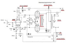
Some load resistors from the OT UL taps to the output tube screen grids. A couple of 12HL7 tubes configured as a differential stage drives the output tube screen grids with its plates. The output tube grid1s get wired to the 12HL7 grid1s too, with adjustable attenuators. And the output tube plates get wired to the 12HL7 screen grids with a set of approx. 3 to 1 attenuators, Then a grid1 bias set network for the 12HL7s for setting avg. operational voltage at the output screen grids. All connnected up with phasing for N Fdbk. The 12HL7 diff. stage maintains constant gain control of the output tubes versus the grid drive signals. REAL Ultra Linear for a change.
This configuration depends on the 12HL7s having good linear internal triode function, which they do:
Last edited:
Yeah, roughly like that. A few bias and attenuator tweaks needed. Oh, that schematic is using resistive plate to grid1 Fdbk to the diffl. stage to set gain. the above desc. used plate Fdbk to the diffl. scrn grids to set gain via the internal triode of he 12HL7s or whatever. The Mosfet followers might not be needed, depending on the output tube screen currents. An output tube like say 21LG6A, with low screen current and low screen voltage would be ideal.


Last edited:
Is that essentially acting like a tube based voltage regulator on the screens of the output tubes?
I agree that ultralinear was a great marketing term. It should be fixed or just abandoned.
I agree that ultralinear was a great marketing term. It should be fixed or just abandoned.
Yes, sort of.
More like UL, except it tweaks the screen Vs some to get -accurate- linear gain. better than standard UL. (regular UL gives high 2nd H+ .., which should cancel in P-P ) A fixed voltage on the screens from just a V regulator would give 3/2 power law from the output tubes, which then needs local or global N Fdbk to fix back to linear. Class A would fix the even harmonics at least.
More like UL, except it tweaks the screen Vs some to get -accurate- linear gain. better than standard UL. (regular UL gives high 2nd H+ .., which should cancel in P-P ) A fixed voltage on the screens from just a V regulator would give 3/2 power law from the output tubes, which then needs local or global N Fdbk to fix back to linear. Class A would fix the even harmonics at least.
Very neat arrangement. Regulating to an optimal voltage, not a fixed voltage. Thank you for sharing.
The same could be done just using a diffl. driver stage in front of the Outputs, with local N Fdbks back to the driver cathodes say. The Active UL idea was just a scheme at the time to see what UL should -actually- be putting on the screen grids to get real linear output. Something to look at on the scope for curiosity. But it could make an interesting add on module for simple amplifiers.
Usual UL converts the pentode outputs to internal triode outputs with a somewhat higher mu due to the 43% UL atten. factor. Looking at most pentodes set up as triodes reveals a significant 2nd H content + some higher Hs. The UL curves still show an increasing gm (and mu ) effect at higher output current. The Active UL idea just fixes the mu variation.
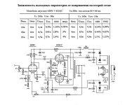
KT77 was specifically set up for UL use, but notice the increasing spacing between curves at higher current.
https://www.audiomatica.com/tubes/kt77.htm
The biggest problem with standard UL was that it runs out of steam when high current is needed, as Stu Hegeman noted about the Citation II. So I still favor a fixed Scrn V with a linearising driver stage in front. That may however make it sound more SS like. When the distortion goes down toward zero, the usual tube sounds are gone.
Usual UL converts the pentode outputs to internal triode outputs with a somewhat higher mu due to the 43% UL atten. factor. Looking at most pentodes set up as triodes reveals a significant 2nd H content + some higher Hs. The UL curves still show an increasing gm (and mu ) effect at higher output current. The Active UL idea just fixes the mu variation.
KT77 was specifically set up for UL use, but notice the increasing spacing between curves at higher current.
https://www.audiomatica.com/tubes/kt77.htm
The biggest problem with standard UL was that it runs out of steam when high current is needed, as Stu Hegeman noted about the Citation II. So I still favor a fixed Scrn V with a linearising driver stage in front. That may however make it sound more SS like. When the distortion goes down toward zero, the usual tube sounds are gone.
Last edited:
So jeff 429 are you any the wiser on your choice of tube amp.probably not .threads like this ramble over and over.there are plenty of opions and seudo factiods.reality is go ahead, decide what you want and build it.you wont know untol its up and running how it sounds with your speakers and being diy you change the amp in some many ways to your preferance sonicaly. Good luck on your journey. Ive been building tube amps most of my life and what have now is stunning but it took a long time to get there.

So now we know the output of the OP's tube amp. Any idea of the driver stage?
I was going to suggest improved driver PCBs for Dyna Mk III. Such as this one PCB1A (just the driver, not the UL output).
I was going to suggest improved driver PCBs for Dyna Mk III. Such as this one PCB1A (just the driver, not the UL output).
PCB1A Looks like an IC design with lots of loop gain for global N FdbK. You will need a pretty good OT.
For a beginner Amp, I would suggest using some inexpensive output tubes that are already fairly linear and low output impedance, like JJ KT77s in P-P triode mode. Edcor or whatever OT. KT77 in triode: ra 1050 Ohm, P-P OT around 5K Ohm in class AB1. see GEC datasheet for triode Amp example, 18 Watt out.
Most any front end would do then. N Fdbk optional.
https://www.audiomatica.com/tubes/kt77.htm
Last edited:
A UL/Triode switch would allow 25 Watt/ 18 Watt output
The "GEC Application report #14, Amplifier circuits for KT77" gives some complete amplifiers.
The "GEC Application report #14, Amplifier circuits for KT77" gives some complete amplifiers.
For a beginner Amp, I would suggest using some inexpensive output tubes that are already fairly linear and low output impedance,
why does a beginner need a circuit with a bunch of vacuum tubes for 18 watts?
in a pentode one double triode + 2 output stage tubes will provide more power and better quality?
compare prices of kt77 and 6p41s
the circuit is simple and extremely high-quality, provided that it is properly configured using a spectrum analyzer
no circuits with 4-6 triodes in front of the output stage can compare
PS: the best amplification stage is the one that does not exist - only in this way it does not introduce distortion into the amplified signal 🙂))
note how the parameters of the THD change depending on the supply voltage of the second grid
Attachments
Attachments

While I'm a big fan of the 6P41S, there are a couple of issues:compare prices of kt77 and 6p41s
1) Not a current production tube. You need to rely on NOS.
2) Magnoval socket, you won't find a PCB kit for it.
Other than that it is a great tube. Pretty linear triode-strapped. I've run it in a single ended, 380Vak, 55mA, no sweat.
пока их достаточно от производства СССР
за один КТ88 сколько будет стоить 6п41с?
Зачем нужна печатная плата в ламповом усилителе?
зачем однотактный, если есть замечательный ПП?
за один КТ88 сколько будет стоить 6п41с?
Зачем нужна печатная плата в ламповом усилителе?
зачем однотактный, если есть замечательный ПП?
Attachments

6P41S 14 Watt, 8400 gm, 100 mA max DC $5 to $10 now
JJ KT77 25 Watt, 10500 gm, 180 mA max DC $28
21LG6A 28 Watt, 11500 gm, 315 mA max DC $4
GEC has an Amp up to 60 Watt using the KT77 in UL
KT77 has the best Triode curves, an Octal socket, current production
Two ECC83 or ECC82 can do the front end for the GEC AMPS.
The OT, PWR Xfmr and case are where the $$ is.
As noted above, the OP is not here.
Some newcomers want something tried and tested for their first amp, and don't have a lot of experience with tube amps. For those, I would not recommend a 6P41S/6P45S etc. A well supported kit, with many builders, PCB based can be a godsend.
Then there are others with more experience, or pretty adventurous, where they think about starting with an 845 SE with 1200V B+. For those the sky is the limit, and are ready to experiment with everything.
In my particular case I'm somewhere in the middle, and for my first amp I used a well know schematic and well known tubes, and got exactly the expected result. That's what I always recommend, if one is starting with valves. Just go first for simple and predictable stuff, enjoy the result, then go ahead and build something else.
PS Please use English. Some of us are fluent in Russian, but not everyone.
That is one very interesting solution to drive EL86 in UL mode , I like it because half of 6CG7 is configured as cathode follower which ensure low output impedance supply for EL86 screen grid with his constant dynamic wandering impedance , think that g2 drive level or UL % level can be easy adjusted to optimum by changing mutual values of those two 100K grid resistors , btw, I wonder is this let`s say
active UL system can be also used for PP amps ? , probably yes ...I have made something similar in a push pull amp. I used mosfets for the G2 buffer. The amp used small TV sweep (line output) tubes which have a low Vg2 max rating, so I used a fixed DC voltage to bias up the mosfet and an adjustable pot for the AC signal from the plate. It was a breadboard experiment before I discovered what I now call UNSET. The UNSET concept worked and sounded better to me. Both experiments were run with the same 6600 ohm guitar amp quality OPT's which did not have UL taps. They are low buck transformers that I have a lot of. They work well with a low impedance drive source, and UNSET is a simulated triode which has a lower plate impedance than simulated UL. Both gave similar power outputs once the B+ was above 300 volts. The simulated UL had problems at low voltages due to low screen voltages when the plate is driven downward. UNSET runs a regulated fixed G2 voltage.I wonder is this let`s sayactive UL systemcan be also used for PP amps ? , probably yes ...
6P41S 14 Watt, 8400 gm, 100 mA max DC $5 to $10 now
14 watts for 6p41s is funny information - although according to the passport it is so - you have indicated everything correctly
this is an understated value so that there are no claims to the manufacturer
For example: the 6p3s lamp according to the passport is no more than 250 volts
but in fact it works for many years at 370 anode voltage and 55 mA current
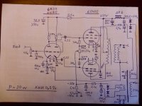
PS: the circuit I provided is 20 watts in Class A
- Home
- Amplifiers
- Tubes / Valves
- What tube amp to build