I get the same error message with your project. I would try the older Gmsh (4.6.0 is all I've ever used).
Last edited:

I'm just starting to get a grip on interpreting the graphs but to me it looks like down to 500-600hz there's not a lot of difference?
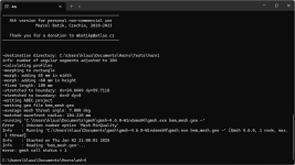
I downloaded Gmsh 4.6.0 an re-run the latest config file again. The error message changed, see attachment. ;-)I get the same error message with your project. I would try the older Gmsh (4.6.0 is all I've ever used).
I really appreciate your support!
Attachments
Last edited:
There's probably still a Gmsh config file somewhere, created by the newer Gmsh version, that the old version now tries to read and don't understand it.
Try to start Gmsh app and "Save Options as Default". The file is in C:\Users\...\AppData\Roaming\gmsh-options" in my case. Maybe you could also try to delete it first.
Try to start Gmsh app and "Save Options as Default". The file is in C:\Users\...\AppData\Roaming\gmsh-options" in my case. Maybe you could also try to delete it first.
Yes, not a big difference. The larger the waveguide, the lower it controls directivity - that's a general rule of thumb but here the differences are not so big.I'm just starting to get a grip on interpreting the graphs but to me it looks like down to 500-600hz there's not a lot of difference?
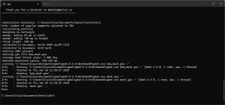
Thank you very much! Gmsh 4.6.0. is now working. but still the same error in ABEC3 when i try to open the .abec file. :-(There's probably still a Gmsh config file somewhere, created by the newer Gmsh version, that the old version now tries to read and don't understand it.
Try to start Gmsh app and "Save Options as Default". The file is in C:\Users\...\AppData\Roaming\gmsh-options" in my case. Maybe you could also try to delete it first.
Furthermore I recognized that ath does not output the final height and width of the horn in the command line as I saw in your tutorial. Can this be a hint that something went wrong?
Can I get a newer version of a free ABEC3 version somewhere? I noticed you used ABEC 3 3.6.0 b7 in your use guide. Maybe this may help?
Attachments
What happens when you hook up a transformer the other way - something happens with the impedance and whats being gained/attenuated...
//
I was wondering how the impedance curve of the same BMS driver on the bigger horn looks. To find out if the room can still be seen in this.You mean a photo? 🙂
Is this how it should look like?They are included in the latest zip package.
You can also set
FusionRotaryProfile = {
}
in the script and use ProfileImport with the generated *.afp file.
When import as addin:
When import as script:
No, that looks like some empty script. I don't know what you found but attached is the correct AthProfileImport script (it's really a Script, not an Add-In).Is this how it should look like?
Attachments
What do you mean? It's basically still the same. It may not yet be properly calibrated, I was just curious if it's cleaner or not. It's not, IMO.
Have you also lowered the resistance in the measurement rig?Measured with a power amplifier with much lower series resistance. Now what? 🙂
I will send the relevant ABAC project files to the developer of ABAC. Maybe this will bring some new input for this issue.@Klaus983 - I'm out of ideas, I'm afraid.
maybe a dumb question but if one chooses to attenuate the compression driver with an autoformer to match a woofer does a parallel swamping resistor not flatten the impedance variances to a large degree?
A parallel resistor can flatten the driver impedance to a large degree when using an autoformer. Also it is possible to use a tapped inductor as both a crossover component and the autoformer. For example a second order filter will have an inductor between the driver and ground. You can tap some off the shelf ferrite core inductors by unwinding some of the wire and adding a tap.
Sure, I dusted off my old equipment, it will be something like 10R but I need to check.Have you also lowered the resistance in the measurement rig?
- It's an interesting topic for sure. As I understand, to eliminate the effects of driver+horn acting as a microphone, we would need as low impedance as possible connected to the driver, right? Can't think of anything lower than a directly connected solid-state amp, what always remains is the voice coil itself. Is there a way how to quantify the effect then? What does an autoformer do in this regard?
But maybe the first question should be is it actually a problem at all? I saw a lot of such "noisy" impedances of horns on the web but nobody ever paid attention to it, which I found strange but until now I had no own experience. So what's really going on?
Last edited:
- Home
- Loudspeakers
- Multi-Way
- Acoustic Horn Design – The Easy Way (Ath4)