In the PCM2DSD hardware, the oversampling process introduces the most significant delay. Since 128 data points are required, this results in a delay of approximately 64 samples. At 44.1 kHz, this equates to around 1.5 milliseconds. At 88.2 kHz, the delay is halved, and at 176 kHz, it is reduced to about 0.36 milliseconds, which is the shortest delay. While this might feel a bit unusual, the calculation aligns with the buffer size, so it is accurate.Hi all ... I have been following this interesting thread on & off for some time now and this morning have been reading some way into the thread trying to find some information about the latency - or delay - of this circuitry but not really finding it? Since I also use my DAC for a digital piano the delay matters in this context ...
Thanks for any info on this 😉
Jesper
However, since playback involves a PC, the overall delay will also include the latency from the PC's data transfer. This latency depends more on the sampling frequency and is also influenced by the buffer size of the USB device, which can vary significantly depending on the environment. For instance, the miniDSP USBStreamer can accommodate a buffer of up to 8k samples. Using a larger buffer reduces the risk of audio dropouts, so I typically set it to 8k. In this case, the delay is directly proportional to the buffer size, resulting in a delay equivalent to 8k samples.
That said, the actual delay depends on various factors and cannot be determined precisely. The maximum delay is the equivalent of 8k samples. 8k buffer may have less delay than 8k. As a result, the delay on the PC side is likely to be more significant and more challenging to calculate accurately.

Audio terminology often lacks clear definitions, and SNR (Signal-to-Noise Ratio) is one of them. Using an AP (Audio Precision) measurement device, the SNR is around 125 dB, which is likely the number used for comparison with other devices. However, there’s a trick involved: many modern DACs increase their output levels to improve their apparent SNR. While older DACs typically had an output level of 2 Vrms, many newer ones reach 5 Vrms. Since SNR is the ratio of signal to noise, a higher output level inherently improves the SNR.Perhaps interesting, the new 1-bit "Topping D90 III Discrete" dac is claimed to have 130dB DNR and 131dB SNR.
https://www.toppingaudio.com/product-item/d90-iii-discrete
With a residual noise level of about 2 µVrms, an SNR of 125 dB seems plausible. This residual noise level of 2 µVrms is close to the physical limits of DAC performance due to thermal noise. Achieving better performance would require cooling, so 2 µVrms is generally sufficient.
What raises questions, however, is that in the case of a 1-bit DAC, the output level should decrease by about -6 dB, resulting in a worse SNR. For instance, my measurement DAC, the D90 (AK4499EQ), shows worse SNR performance with DSD input than I2S input. A new trick may have been developed to counteract this limitation, IMO.
Playback doesn't have to involve a PC. There are digital pianos with USB audio output. But as you said some buffering may be needed with asynchronous USB audio. Most USB-I2S bridges have buffers.However, since playback involves a PC, the overall delay will also include the latency from the PC's data transfer.
When the DAC output is too high it is a problem. Most of the power amplifiers are too sensitive. To get comfortable loudness you need to use volume regulator that makes SNR of entire system quite bad. I modified my amplifier to have gain only 12dB, but I’m still using half or less volume, waisting at least 6 to 20dB of the dynamic range.A new trick may have been developed to counteract this limitation, IMO.
The good trick is to amplify the signal in the DAC reconstruction filter to 5..10VRMS, getting maximal possible SNR and then attenuate it to the required level in the DAC output inverting/differential stage. Because of using low resistors in the feedback of the attenuating stage (~200R), the losses of SNR could be minimized. But of course, you need to use OPAMPs like ADA4898 or OPA1612 with <1nV/rtHz noise and very powerful output, if you want to have any benefit.
Last edited:
Is there by chance a .bit file for this version?This is the DSD128 version of PCM2DSD.
Only a limited number of DACs support DSD512, and while it doesn’t offer better numerical performance, it allows for lower modulator orders, resulting in higher maximum stable amplitude(MSA). So, I designed a DSD512(3rd-order) targeting monolithic DACs like the AK4499EQ.
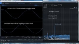
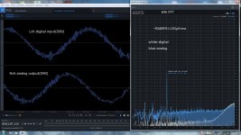
Pic 2 shows the digital and analog outputs for a 1 kHz (0 dBFS). Numerically, the digital performance is similar to DSD256, but the quantization noise is reduced. However, the analog output shows worse THD and SNR than DSD256, though still within acceptable limits. The performance of discrete DACs is uncertain.
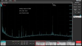
Pic 3 displays the out-of-band noise. The level of 706 kHz for stabilizing is higher than in DSD256. Using a 1.4 MHz carrier might be better. Many other spectral components originate from the D90’s SMPS; similar artifacts appear even with I2S input. Pics 4 and 5 compare the output at -90 dBFS, showing no significant difference from DSD256, though DSD128 performs noticeably worse.
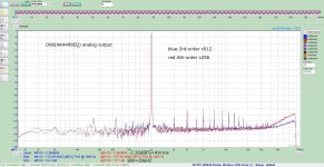
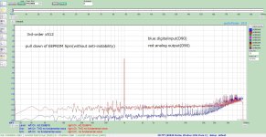
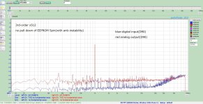
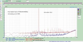
Pics 6 and 7 illustrate stability at low levels (-60 dBFS). As with DSD256, introducing a 706 kHz carrier results in sideband-like components but stabilizes the quantization noise. Without the carrier, DSD512 exhibits significant noise fluctuations at roughly one-second intervals. While these variations are likely below the perceptual threshold, avoiding large fluctuations is preferable. Distortion components increase above 20 kHz due to overlap with quantization noise, but the distortion level remains similar to lower frequencies. Pic 8 compares DSD256 (4th-order) and DSD512 (3rd-order), highlighting differences in quantization noise levels.
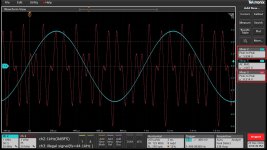
Pic 9 is interesting. The blue trace shows a 1 kHz (0 dBFS) signal with a D90 output of approximately 2 Vrms (Single End), corresponding to about 6 Vpp, which clips at this level. The red trace represents a deliberately constructed signal at 44.1 kHz sampling to produce maximum amplitude. That's why this is "illegal". Despite expectations, the D90 extends the output to 8.5 Vpp, approximately 3 dB above the clipping threshold. Both signals are PCM over USB.
Some DACs, like the Benchmark DAC3, intentionally allow a 3 dB headroom, but most DAC chips clip at 0 dBFS, resulting in significant distortion. Consequently, CDs under the "loudness wars" often clip and distort heavily. However, the D90 seems to avoid this, likely due to the AK4499EQ's characteristics. This could result in an audible improvement when playing CDs.
With DSD, the situation becomes more complex. The DSD128 (5th-order), DSD256 (4th-order), and DSD512 (3rd-order) files use a gain setting of 0 dBFS (PCM) = -6 dBFS (DSD), ensuring no clipping during oversampling.
However, the inherent MSA exists in 1-bit DSM. For DSD128 (5th-order), saturation occurs at around -5 dBFS, leaving only about 1 dB of headroom when oversampled signals exceed 0 dBFS. This means up to +1 dBFS (PCM) is safe. The limit for DSD256 (4th-order) is around +2 dBFS, while DSD512 (3rd-order) extends to approximately +3.2 dBFS. This increased headroom is a key advantage of 3rd-order, making a 5th-order DSD512 implementation nonsense.
Thus, when driving the D90 with DSD, DSD512 will likely offer the best audible performance for CDs. The numerical performance degradation is negligible, and The high MSA makes it a strong candidate. Ultimately, the choice depends on personal preference, but DSD512 is my best option.
Pic 2 shows the digital and analog outputs for a 1 kHz (0 dBFS). Numerically, the digital performance is similar to DSD256, but the quantization noise is reduced. However, the analog output shows worse THD and SNR than DSD256, though still within acceptable limits. The performance of discrete DACs is uncertain.
Pic 3 displays the out-of-band noise. The level of 706 kHz for stabilizing is higher than in DSD256. Using a 1.4 MHz carrier might be better. Many other spectral components originate from the D90’s SMPS; similar artifacts appear even with I2S input. Pics 4 and 5 compare the output at -90 dBFS, showing no significant difference from DSD256, though DSD128 performs noticeably worse.
Pics 6 and 7 illustrate stability at low levels (-60 dBFS). As with DSD256, introducing a 706 kHz carrier results in sideband-like components but stabilizes the quantization noise. Without the carrier, DSD512 exhibits significant noise fluctuations at roughly one-second intervals. While these variations are likely below the perceptual threshold, avoiding large fluctuations is preferable. Distortion components increase above 20 kHz due to overlap with quantization noise, but the distortion level remains similar to lower frequencies. Pic 8 compares DSD256 (4th-order) and DSD512 (3rd-order), highlighting differences in quantization noise levels.
Pic 9 is interesting. The blue trace shows a 1 kHz (0 dBFS) signal with a D90 output of approximately 2 Vrms (Single End), corresponding to about 6 Vpp, which clips at this level. The red trace represents a deliberately constructed signal at 44.1 kHz sampling to produce maximum amplitude. That's why this is "illegal". Despite expectations, the D90 extends the output to 8.5 Vpp, approximately 3 dB above the clipping threshold. Both signals are PCM over USB.
Some DACs, like the Benchmark DAC3, intentionally allow a 3 dB headroom, but most DAC chips clip at 0 dBFS, resulting in significant distortion. Consequently, CDs under the "loudness wars" often clip and distort heavily. However, the D90 seems to avoid this, likely due to the AK4499EQ's characteristics. This could result in an audible improvement when playing CDs.
With DSD, the situation becomes more complex. The DSD128 (5th-order), DSD256 (4th-order), and DSD512 (3rd-order) files use a gain setting of 0 dBFS (PCM) = -6 dBFS (DSD), ensuring no clipping during oversampling.
However, the inherent MSA exists in 1-bit DSM. For DSD128 (5th-order), saturation occurs at around -5 dBFS, leaving only about 1 dB of headroom when oversampled signals exceed 0 dBFS. This means up to +1 dBFS (PCM) is safe. The limit for DSD256 (4th-order) is around +2 dBFS, while DSD512 (3rd-order) extends to approximately +3.2 dBFS. This increased headroom is a key advantage of 3rd-order, making a 5th-order DSD512 implementation nonsense.
Thus, when driving the D90 with DSD, DSD512 will likely offer the best audible performance for CDs. The numerical performance degradation is negligible, and The high MSA makes it a strong candidate. Ultimately, the choice depends on personal preference, but DSD512 is my best option.
Attachments
-
 pic9_intersample_D90.jpg259.4 KB · Views: 69
 -
 pic8_DSD_4th_3th_1kHz_0dB.jpg270.4 KB · Views: 69
 -
 pic7_DSD_3th_1kHz_-60dBwithout.jpg259.9 KB · Views: 67
 -
 pic6_DSD_3th_1kHz_-60dBwith.jpg266 KB · Views: 68
 -
 pic5_3th_-90dBFS_LPF.jpg282.9 KB · Views: 61
 -
 pic4_3th_-90dBFS.jpg290.3 KB · Views: 59
 -
 pic3_3rd-order_1MHZ_FFT.jpg186 KB · Views: 63
 -
 pic2_DSD_3th_1kHz.jpg289.8 KB · Views: 60
 -
pcm2dsd_x512_mcsANDbit.zip277.6 KB · Views: 49
Would you please describe your preferred measurement technique for the noise bursts?Without the carrier, DSD512 exhibits significant noise fluctuations at roughly one-second intervals.
I tested by inputting a file with levels gradually decreasing by 10 dB every five seconds, such as 1 kHz (0 dBFS), 1 kHz (-10 dBFS), ..., 1 kHz (-130 dBFS), and 1 kHz (-140 dBFS). After final editing, the digital signal is placed in the left channel (Lch) and the analog signal in the right channel (Rch). This is how the file looks with and without instability correction applied. With a file of about one minute, you can observe the degree of noise fluctuation.
https://www.dropbox.com/scl/fi/5s5a...ey=jcym9diudi8t5r2hg5mvttm9p&st=b28u1s5i&dl=0
https://www.dropbox.com/scl/fi/nhrj...ey=7np7b8x1327cwymqvnf6gpesu&st=h2ool081&dl=0
https://www.dropbox.com/scl/fi/5s5a...ey=jcym9diudi8t5r2hg5mvttm9p&st=b28u1s5i&dl=0
https://www.dropbox.com/scl/fi/nhrj...ey=7np7b8x1327cwymqvnf6gpesu&st=h2ool081&dl=0
@xx3stksm : Just returned from my Christmas vacation and have read your reply in post #1103 above - thanks for your feedback! So, from reading what you write I suppose it is not that easy to "calculate" the delay theoretically - it probably should be tested out in practice. But my guess would be that if the sampling frequency is set relatively high (e.g. 96 kHz or above) the PCM2DSD would not in itself contribute much to the overall delay. Very good to know - thanks for your helpfulness 😉
Cheers & all the best for the New Year!
Jesper
Cheers & all the best for the New Year!
Jesper
Hi @xx3stksm
I tried your DSD512 modulator with Marcel's RTZ FIRDAC. To be fully honest, the instrument sounds are a little blurred together so that individual low level instrument sounds are masked. Also, sound stage lateral localization and sound stage depth cues are mostly missing. Not to feel bad, Marcel's DSD512 modulator has similar effects at this point in time.
The best so far I have heard is the latest version of the DSD256 modulator posted by @PJotr25. I know that I worked with Piotr for some time, listening to dozens of variations before identifying the best sounding couple of versions. After that @bohrok2610 provided some additional measurement information that led to a further reduction in FFT spurs for Piotr modulator, and to lower levels of audible distortion.
IOW, it seems to me that theory can only get so close to optimization, then empirical methods may lead to some more optimal local solution to the human perceptual SQ problem. If any interest I am willing and able to work with you and or Marcel towards seeing if the performance of Piotr's modulator can be duplicated or even improved upon with one of the DSD512 modulators.
Thank you for sharing your work in any case. Its good when people around the world can work together towards better audio.
Best,
Mark
Hi MarkW4
Thank you for the listening test. When listening to DSD512 on a discrete DAC, achieving a THD+N exceeding 90dB is unlikely, so finding individual sounds difficult to distinguish is an expected outcome. In my setup, which is a multi-system configuration, I use DSD64 for low frequencies and DSD128 for mid and high frequencies. Even DSD256 doesn’t yield favorable results. In my environment, the THD+N value generally correlates with sound quality, so I select three configurations based on this value and finalize the choice through listening.
The configuration adjustments are primarily on the DAC side, not the modulator. Once the order and OSR of the modulator are determined, an optimal formula exists, leaving only the stability adjustment for low-level inputs as a variable. Oversampling is also formulaic and shows minimal impact when altered. On the DAC side, the setup uses a 16-tap FIR filter, and adjusting the tap arrangement results in significant changes.
For instance, with a 4-tap configuration, arranging taps as x0,x1,x2,x3 versus x1,x0,x2,x3
can produce notable differences. With 16 taps, the THD+N can vary by 12dB between the best and worst configurations. While testing all possible combinations is impractical, even comparing 64 configurations can reveal significant differences. The FIR elements are connected to the FPGA output, making it easy to modify the combinations. A microcontroller writes the settings during power-on.
Therefore, sound quality adjustments are determined primarily by the FIR filter arrangement in the DAC rather than the modulator. These settings are specific to each DAC and require individual tuning for each unit. In multi-system setups, multiple units must be adjusted. However, once configured, re-adjustments are rarely needed. For DSD64, achieving sixth-order modulation to suppress quantization noise is slightly challenging for the xc6slx9. Although the OSR is low, multiplexing the L and R channels might make it feasible. The quantization noise can be made significantly smaller than that of SACD. Based on its development era, SACD likely uses considerably outdated modulation techniques.
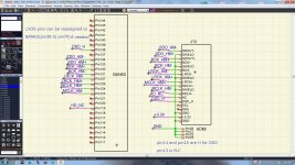
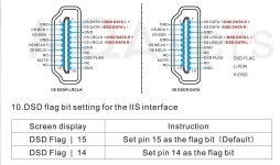
DSD256 and DSD512 are primarily intended for monolithic DACs like the AK4499EQ, and the signal is transmitted to the DAC via HDMI. In the three uploaded files, as shown in the accompanying diagram, the FPGA outputs LVDS signals. Adding a connector allows direct connection to a DAC with HDMI input. However, board design is necessary. The HDMI pin assignments may vary slightly by manufacturer, but setting pins 14 and 15 to high (H) should enable DSD input while setting them to low (L) would result in I2S input.
Thank you for the listening test. When listening to DSD512 on a discrete DAC, achieving a THD+N exceeding 90dB is unlikely, so finding individual sounds difficult to distinguish is an expected outcome. In my setup, which is a multi-system configuration, I use DSD64 for low frequencies and DSD128 for mid and high frequencies. Even DSD256 doesn’t yield favorable results. In my environment, the THD+N value generally correlates with sound quality, so I select three configurations based on this value and finalize the choice through listening.
The configuration adjustments are primarily on the DAC side, not the modulator. Once the order and OSR of the modulator are determined, an optimal formula exists, leaving only the stability adjustment for low-level inputs as a variable. Oversampling is also formulaic and shows minimal impact when altered. On the DAC side, the setup uses a 16-tap FIR filter, and adjusting the tap arrangement results in significant changes.
For instance, with a 4-tap configuration, arranging taps as x0,x1,x2,x3 versus x1,x0,x2,x3
can produce notable differences. With 16 taps, the THD+N can vary by 12dB between the best and worst configurations. While testing all possible combinations is impractical, even comparing 64 configurations can reveal significant differences. The FIR elements are connected to the FPGA output, making it easy to modify the combinations. A microcontroller writes the settings during power-on.
Therefore, sound quality adjustments are determined primarily by the FIR filter arrangement in the DAC rather than the modulator. These settings are specific to each DAC and require individual tuning for each unit. In multi-system setups, multiple units must be adjusted. However, once configured, re-adjustments are rarely needed. For DSD64, achieving sixth-order modulation to suppress quantization noise is slightly challenging for the xc6slx9. Although the OSR is low, multiplexing the L and R channels might make it feasible. The quantization noise can be made significantly smaller than that of SACD. Based on its development era, SACD likely uses considerably outdated modulation techniques.
DSD256 and DSD512 are primarily intended for monolithic DACs like the AK4499EQ, and the signal is transmitted to the DAC via HDMI. In the three uploaded files, as shown in the accompanying diagram, the FPGA outputs LVDS signals. Adding a connector allows direct connection to a DAC with HDMI input. However, board design is necessary. The HDMI pin assignments may vary slightly by manufacturer, but setting pins 14 and 15 to high (H) should enable DSD input while setting them to low (L) would result in I2S input.
Attachments
Hi @xx3stksm
I tried your DSD512 modulator with Marcel's RTZ FIRDAC. To be fully honest, the instrument sounds are a little blurred together so that individual low level instrument sounds are masked. Also, sound stage lateral localization and sound stage depth cues are mostly missing. Not to feel bad, Marcel's DSD512 modulator has similar effects at this point in time.
The best so far I have heard is the latest version of the DSD256 modulator posted by @PJotr25. I know that I worked with Piotr for some time, listening to dozens of variations before identifying the best sounding couple of versions. After that @bohrok2610 provided some additional measurement information that led to a further reduction in FFT spurs for Piotr modulator, and to lower levels of audible distortion.
IOW, it seems to me that theory can only get so close to optimization, then empirical methods may lead to some more optimal local solution to the human perceptual SQ problem. If any interest I am willing and able to work with you and or Marcel towards seeing if the performance of Piotr's modulator can be duplicated or even improved upon with one of the DSD512 modulators.
Thank you for sharing your work in any case. Its good when people around the world can work together towards better audio.
Best,
Mark
Hi Mark,
A few questions - How would you rate your best DSD / RTZ DAC against a chip based one (assuming the 4499). Have you had a chance to listen to Topping D90 III Discrete yet?
I'm intrigued how they are achieving such high DR with 2x16 elements (Bal). Does anyone here know what freq they are switching at?
Keep tweaking, the results are interesting, especially if you can eventually find some kind of subjective / objective correlation.
Cheers
Terry
Hi Terry,
Haven't listened to D90 III Discrete yet, but know of some reports about the SQ being very good, especially for the price. However, I believe its quite unlikely it can reproduce sound stage like Marcel's RTZ dac can when driven by ultra-low phase noise Acko clocks. It can be pretty deep and holographic. One thing I know can strongly affect DNR is choice of output resistors. Some thin film resistors have higher excess noise than others. I would also say that Marcel's RTZ dac with transformer output stage and Acko clocks completely outclasses the original Topping D90 with AK4499EQ.
Anyway, apparently Topping designed a modulator that tends to cancel out Vref noise by phase inverting internal output stage every clock cycle, or something more or less like that. Don't see how they could do a trick like that to cancel clock phase noise as it affects ITD though.
Pictures of it look pretty much like a discrete FIRDAC with a local clock:
Last edited:
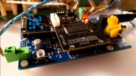
Trying to connect this processor to a FifoPiQ7 board.
Anybody has succeed on using a FifoPi? Any concealed trick?
I take I2S signal from the PCM2DSD output interface and connect those three LRCK, BCK and DATA to iancanada board J1 GPIO originally intended to connect a Rasperry Pi as input.
It is a green light under the clocks, but till now unable to suck the signal out of it.
- Home
- Source & Line
- Digital Line Level
- Simple DSD modulator for DSC2