Hi everyone! This is my first post, I am quite a newbie in electronics, so please forgive my ignorance.
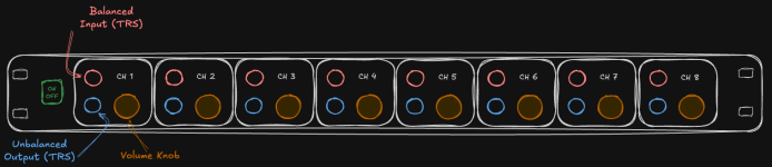
My idea is to make a headphone amplifier that takes one balanced mono input and delivers one unbalanced output. But I want to make 8 of these and put them in parallel! Here is the sketch:

I would be used to drive in-ear monitors, each musician has a bodypack with a passive volume control and a 3.5mm jack to plug their headphones, something like the Behringer PM1.
The input comes from my Behringer XR18 auxiliary outputs, they are mono and balanced, here are the specs:

The output also is mono but unbalanced. The headphones used for in-ear monitoring are normally 32 ohms.
Ah, I forgot to mention: I want to make it as cheap as it can be 🤑 , but it would be great to have a clear sound with little or no noise.
So, what do you suggest?
Many thanks!
My idea is to make a headphone amplifier that takes one balanced mono input and delivers one unbalanced output. But I want to make 8 of these and put them in parallel! Here is the sketch:
I would be used to drive in-ear monitors, each musician has a bodypack with a passive volume control and a 3.5mm jack to plug their headphones, something like the Behringer PM1.
The input comes from my Behringer XR18 auxiliary outputs, they are mono and balanced, here are the specs:
The output also is mono but unbalanced. The headphones used for in-ear monitoring are normally 32 ohms.
Ah, I forgot to mention: I want to make it as cheap as it can be 🤑 , but it would be great to have a clear sound with little or no noise.
So, what do you suggest?
Many thanks!
Attachments
I actually reckon you might be struggling to do 8 channels, power supply, enclosure and all the hardware for the (AU) $249 the H8000 costs.
See what the others come up with.
See what the others come up with.

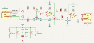
The cheapest / simplest I can think of would be 4 x NE5532 for 8 single opamp balanced inputs (at line level I don't think you need to use anything more sophisticated than this) and 4 x NJM4556 for 8 mono headphone drivers (this opamp has been measured to handle 15R loads well here). There are better parts in SMD but I assume as a newbie you'd prefer through-hole parts. Something like this (10k balanced input impedance and a gain of ~5 which should be plenty) with a suitable +/-15 V power supply:

Note that the bulk of the cost will be the box, connectors, pots, knobs, etc.
Note that the bulk of the cost will be the box, connectors, pots, knobs, etc.
Hey, here is my version using the KiCad. I probably made some mistakes, so please feel free to correct me.

I have some questions though:
I have some questions though:
- What type of capacitors should I use? Ceramic? Electrolytic? Do I need to worry about their polarity?
- I don't know where to connect the GND of the output.
- I reused the power supply schematic from another design. Should I keep all those capacitors, or can I safely remove them?
- Last one: why isn't the volume potentiometer (RV1) connected directly to the HOT signal, before the NE5532N? (Just for curiosity)
Attachments
For the power supply, is it better to use an LM7815/LM7915, LT3042 or LM317/337 module? I am probably going to buy one of those from AliExpress. Some require a DC PSU while others have a transformer so I could plug them directly into the AC 220v. Which one would be better?
And, is one module enough to operate the 8 amps? They claim to deliver from 0.75A to 2A, depending on the model.
And, is one module enough to operate the 8 amps? They claim to deliver from 0.75A to 2A, depending on the model.
Last edited:
I thought you said the input is balanced? So make it balanced, or simplify the circuit.
Also, why not use all 6 pins of the input socket? Hint: what happens to the signal coming into the op-amp when the connector is unplugged?
At this stage you should probably build a prototype. Then iron out the bugs, and only then multiply it by 8x.
Also, why not use all 6 pins of the input socket? Hint: what happens to the signal coming into the op-amp when the connector is unplugged?
At this stage you should probably build a prototype. Then iron out the bugs, and only then multiply it by 8x.
I would be used to drive in-ear monitors, each musician has a bodypack with a passive volume control and a 3.5mm jack to plug their headphones, something like the Behringer PM1.
The input comes from my Behringer XR18 auxiliary outputs, they are mono and balanced. The output also is mono but unbalanced. The headphones used for in-ear monitoring are normally 32 ohms.
Ah, I forgot to mention: I want to make it as cheap as it can be 🤑 , but it would be great to have a clear sound with little or no noise.
I suggest you use "quad" opamp chips which contain 4 opamps per package. Then your entire circuit contains only 4 chips (16 opamps, 2 per headphone In/Out). Something like the TLC074. Use one opamp as a balanced input receiver, and the second opamp as a gain stage + IEM output driver. Voila, two opamps per channel, times eight channels. In Ear Monitors generally require very modest drive voltage and drive current, so an unbuffered "weenie" opamp output pin can do the job easily and still meet your modest requirements above. Then the actual hard part of the design will be minimizing the parts count per channel; every resistor or capacitor you eliminate from the circuit, saves you 8 parts on the circuit board.
Study and viciously scour all of the usual sources: Rod Elliott's website "Elliott Sound Products", Douglas Self's "Small Signal Audio Design" textbook, Bob Cordell's second book "Designing Audio Circuits and Systems", looking for minimum parts count (a) differential receiver circuits; and (b) low current, low voltage headphone driver circuits.
The Behringer you seek to duplicate is AC mains powered, but I suggest that in your project you use an "AC to DC wall wart" instead, and leave all of the lethal AC mains stuff inside a different box which you buy instead of build. The wall wart will contain a Switch Mode Power Supply and will be Dirt The Fword Cheap. If you are frightened of wall warts, you could consider (solution 1) or (solution 2). As you see, it costs money to salve and mitigate your voodoo fears.
- At the input, the sleeve should go to the chassis and the ring to R6/C3, which is the (-) input. The tip is correct, to R7/C8 which is the (+) input.
- At the output, connect both tip and ring to the opamp out and the sleeve to ground. Remove R12, I put it in the schematic to represent the headphone load.
1. For the 10u caps use Nichicon Muse ES, they are bipolar so they have no polarity. For the small ones use ceramic NP0/C0G. For the 100n supply bypass, ceramic X7R and place them as close as possible to each opamp chip. For C10/C13, Panasonic FR. These are polar of course, as shown in the schematic.I have some questions though:
- What type of capacitors should I use? Ceramic? Electrolytic? Do I need to worry about their polarity?
- I don't know where to connect the GND of the output.
- I reused the power supply schematic from another design. Should I keep all those capacitors, or can I safely remove them?
- Last one: why isn't the volume potentiometer (RV1) connected directly to the HOT signal, before the NE5532N? (Just for curiosity)
2. See above.
3. Each chip should have a X7R 100n cap next to it with traces as short as possible to the chip supply pins, and each PCB should have a pair of 100u where the supply enters the board, so that's one pair if you put everything in a single PCB, or 4 pairs if you do it with 4 PCBs, each with two channels.
4. Before the NE5532 the signal is balanced, so if you wanted to put the volume pot there, it would have to be dual, which would throw the CMRR out of the window and affect the input impedance, best to put it right after converting the signal to unbalanced and use a single gang pot.
One more thing: for good CMRR, all the 3k and 6k2 resistors should be 0.1% tolerance. These are widely available nowadays in all the usual suppliers.
Last edited:
As a side note, I know the input network looks unnecessarily complicated, but this is to be used in a band environment and here I wouldn't try to save pennies by removing a few resistors and caps. I speak from experience playing bass in various bands for 40 years: each stage is a different world of RF noise, bad wiring, people plugging things where they shouldn't... To me DC protection and RF filtering are the bare minimum and non-negotiable in this application.
Simple 10uF electrolytics that are normally biased could be used by starting with a 19-24V single-sided laptop PSU, and raising the op-amp's centre voltage with a virtual ground. A ±15V lab supply from a wall adapter is not a realistic proposition.
Thank you all and Merry Christmas!
Here is the updated version of the circuit.

I have a few questions, can you please have a look?
Many thanks!
Here is the updated version of the circuit.
I have a few questions, can you please have a look?
- I have considered what abstract said and used all 6 pins of the TRS connector. When no plug is inserted everything is grounded. Is this correct?
- Can I replace the 33pF capacitors with 30pF ones? I already got them.
- Finally, I added a circuit using the LM3915 IC to display the audio level in the output, like a VU meter. Can you please assess that as well?
Many thanks!
For driving 32 Ohms h/p , +/- 5V supply is recommended using 7805/7905 with a small heatsink. Otherwise the NJM4556 may fail.
Read https://www.diyaudio.com/community/threads/the-objective2-o2-headphone-amp-diy-project.193977/
Read https://www.diyaudio.com/community/threads/the-objective2-o2-headphone-amp-diy-project.193977/
I know you have a schematic already, but the OPA1622 could be a pretty strong option for you.
Tom
Tom
Can you dumb it down for me please? Because this circuits is 15v and not 5v. CheersFor driving 32 Ohms h/p , +/- 5V supply is recommended using 7805/7905 with a small heatsink. Otherwise the NJM4556 may fail.
Read https://www.diyaudio.com/community/threads/the-objective2-o2-headphone-amp-diy-project.193977/
Thanks Tom, but I can buy 10 NE5532N and 10 NJM4556 with the cost of 1 OPA1622. Hehe, cheers!I know you have a schematic already, but the OPA1622 could be a pretty strong option for you.
Tom
Oh, I suppose. 🙂 I suppose you also have a source for the (discontinued) LM3915.
An NE5532+output stage composite should perform well.
Tom
An NE5532+output stage composite should perform well.
Tom
1. Yes, that's what he meant.
- I have considered what abstract said and used all 6 pins of the TRS connector. When no plug is inserted everything is grounded. Is this correct?
- Can I replace the 33pF capacitors with 30pF ones? I already got them.
- Finally, I added a circuit using the LM3915 IC to display the audio level in the output, like a VU meter. Can you please assess that as well?
2. Yes, no problem.
3. Not familiar with this IC, sorry. I guess if you've copied the circuit from the datasheet, it should work ok.
Re. using +/-5 V supplies, the circuit will work perfectly fine without changing anything. It's true that for such low headphone impedance you don't need much output voltage swing and the NJM4556 will run much cooler. I've used it with +/-15 V a few times and never had a problem, but never with very low impedance headphones, so yeah, it may be safer to use a lower voltage supply. I guess that's what @availlyrics was referring to, although I didn't read all 291 pages of that thread...
The circuit will work from +/-5V to 15V,Can you dumb it down for me please? Because this circuits is 15v and not 5v. Cheers
BUT the NJM4556 will have difficulty in driving 32 Ohms load at higher voltage with increased power dissipation as the limit is 300mW for SMD, 700mW for DIP & 800mW sor SIP package. So for 32 Ohms load +/- 5V, for 150 Ohms or above load +/- 9 V to +/-15V
Think of something like motor bike gears, you won't drive it uphill on the highest gear.
Furthermore your schematic has 2 gain stage , while only the Ist stage is needed for gain & the and 2nd stage is for buffer.
Read https://nwavguy.blogspot.com/2011/07/o2-headphone-amp.html
https://nwavguy.blogspot.com/2011/08/o2-details.html
nwavguy has done an excellent job , so no point in reinventing the wheel!
If you want , I can redraw the schematic for you with proper component values
Last edited:
- Home
- Amplifiers
- Headphone Systems
- Poor man's Behringer HA8000 (8 headphones amps in parallel)