I have put a prototype together here, but before I turn it on, I have some questions:
- Other than using the multimeter to test for shorts and continuity, which other tests should I run before plugging it?
- Should I check if the 15 volts are leaking through the 1/4 jacks?
- What does happen if I put an unbalanced input instead of a balanced one?
I always check my traces / wires in both directions: signal from input to output and output to input, supply from header to devices and from devices to header. Some times there's a mistake that you miss in one direction and becomes obvious in the opposite one.
Check your supply before connecting it to the header. Make sure the supply connector and header have the V+ and V- the right way round and re-check the polarity of the electrolytics next to the header.
If you have installed sockets for the opamps, it's always prudent to leave them out at first, connect the supply to the header, turn it on and make sure that you have V+ and V- at pins 8 and 4 of each socket and there's no voltage in any of the other pins or anywhere else in the circuit where it shouldn't be, including the input and output jacks, yes.
There's no problem if you use an unbalanced connector, it will work just fine.

Hey everyone! So, here is my test setup:
I have this little FM radio that sends the signal (in this case it is unbalanced) to the input port, a potentiometer for the volume, very cheap headphones on the output port. The power source is the +/- 15v module in the picture.
.jpeg")


I have this little FM radio that sends the signal (in this case it is unbalanced) to the input port, a potentiometer for the volume, very cheap headphones on the output port. The power source is the +/- 15v module in the picture.
Attachments
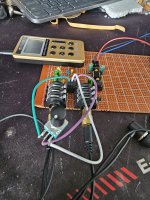
Sorry about the mess and the bad soldering, as you know I am a newbie.
So, as you can imagine it is not working, I have tested continuity, shorts, the ICs are getting the -15v and +15v correctly.
The sound is really loud but it is a constant noise like a "hummmm". Also, after a while, it starts to pulsate. I can hear a pulsating sound from the PSU board (not at first, but after some seconds).
How can I debug this? I think I should have made the circuit more spaced for this prototype....
Cheers
A single 4556 will drive an earpiece to 120db
Use 1 in unity gain and a second to provide any needed gain. Volume pot 5k goes into output op amp from gain op amp.
x2 for both channels
If you need more power, 4 x 4556 in unity tied to output with 4.7 ohm resistors ( 8 outputs per side) 500mA of drive current into 32 ohms is 16 volts or 8 watts of power.
Last edited:
It's really hard to tell, there are quite a few places where solder traces and/or pads look dangerously close to each other.
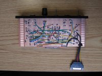
When you're just prototyping, there's no need to place the components and traces so close together, you have plenty of room in that board. If I were you, I'd start again from scratch leaving more space around each component, and the same goes for traces, try if you can to lay them out separated by at least one row of pads, preferably two. Also those traces made entirely of solder are asking for trouble. I've built a few circuits in proto board and I've always used insulated wire (see attached example), cutting and stripping all those wires to the right length is indeed much more tedious than sweeping the soldering iron tip over a row of pads to create a trace, but it's also much less prone to error.
When you're just prototyping, there's no need to place the components and traces so close together, you have plenty of room in that board. If I were you, I'd start again from scratch leaving more space around each component, and the same goes for traces, try if you can to lay them out separated by at least one row of pads, preferably two. Also those traces made entirely of solder are asking for trouble. I've built a few circuits in proto board and I've always used insulated wire (see attached example), cutting and stripping all those wires to the right length is indeed much more tedious than sweeping the soldering iron tip over a row of pads to create a trace, but it's also much less prone to error.
Attachments
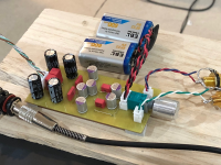
So, I changed my approach and made a prototype using direct connections. I tried to reproduce the following schematic as close as I could:

Here is the result:

The red wire is +15v, the blue is -15v, and the black is ground. The input is on the left, and the output is on the right.
First the good news: it works. I put the audio source at the minimum volume (the FM radio, for now) and it managed to amplify that sound.
The bad news now:
Here is the result:
The red wire is +15v, the blue is -15v, and the black is ground. The input is on the left, and the output is on the right.
First the good news: it works. I put the audio source at the minimum volume (the FM radio, for now) and it managed to amplify that sound.
The bad news now:
- With the input unplugged, it makes a really loud noise, which is odd since everything is grounded.
- The amplification is too low, I turn the potentiomer until its end and it is still very low.
- The potentiometer direction is inverted.
- When there is no sound coming from the source, but with the plug there, I can hear a "humm", it is annoying but not very loud.
The wiring of the volume pot is reversed. ① is GND. Both the schematic and the #43 board seem to be reversed.The potentiometer direction is inverted.
To isolate the problem, try the headphone amplifier section only first.
Noise may be high because the circuit is bare.
The noise may disappear if it is housed in a metal case.
Is there a suitable metal case (to be connected to the GND of the circuit)?
If not, simply placing aluminium foil used in the kitchen underneath may help.
Potentiometers also tend to pick up noise. Try connecting the metal shaft part to GND.
The gain can be increased by lowering the value of R4. However, noise may also increase, so first try the above to see if noise is reduced.
I know this is obvious, but be careful of shorts if you shield the circuit using foil!
Maybe the hum is RFI from the power supply. Those bare component leads in the air make a good antenna.
Maybe the hum is RFI from the power supply. Those bare component leads in the air make a good antenna.
Re: noise:
The SMPS is a guaranteed noise maker, and you have the ± wires floating freely, not even twisted together. They should be twisted and pass through a choke.
The differential input layout "looks" nice but should also be brought together to reduce the loop area, leading up to the op-amp input.
Those 2 black chokes on the SMPS (black circles in heat shrink on opposite sides of the 4 output caps) probably use unshielded I-cores, so they will be emitting RF as well.
The ground wire looks like a long bus, with taps along the length to connect various loads. That's not optimal. You could try a star configuration, so each load has its own line that reduces the effect on other grounding points.
The ground wire looks like a long bus, with taps along the length to connect various loads. That's not optimal. You could try a star configuration, so each load has its own line that reduces the effect on other grounding points.
In a final product, I would have the AC ground connected to the chassis of the amplifier. Should I also connect the DC ground to the chassis?
First you need to make the safety of your prototype less terrifying. Put it in a protective box so you can't accidentally touch high voltages.
You should not even attempt to incorporate an open-frame OEM PSU inside a new product. That makes your product high voltage, and therefore you would have to go through a lot of regulatory / compliance hoops to legalise it before you can sell it. That's one big advantage of including an OTS, OEM power supply that comes in its own little box and somebody else already took care that it meets safety standards. Then, your product is just a low-voltage gadget.
On the technical side, look at what you currently have: the PSU has galvanic isolation. One give-away is the wide 4-pin optocoupler chip next to the transformer. If the PSU blows itself up, the isolation gives some assurance that your 3 red/blue/black wires that you have access to can't get shorted to an AC line.
Unless you are certain that nothing that gets plugged in will be earthed elsewhere, you probably should not earth it. You can of course connect a shield around your circuit to the transformer secondary, but connecting the shield to earth could create ground loops if, say, a soundcard line-out is plugged in.
Oh I'm not going to sell anything, this is for my personal use. But I think i got it, i connect the DC ground to the chassis and leave the PSU separated, preferably in another enclosure, right?
Does this work? It says it uses 4580 opamps.
https://a.aliexpress.com/_m0KrtjV
If you really want to DIY it, OPA1688 or OPA1656 can drive headphones quite nicely.
Here is a single opamp version:

Here is a dual parallel opamp design for a bit more power. Sounds great. The artwork for home etch PCB is available.


https://a.aliexpress.com/_m0KrtjV
If you really want to DIY it, OPA1688 or OPA1656 can drive headphones quite nicely.
Here is a single opamp version:
Here is a dual parallel opamp design for a bit more power. Sounds great. The artwork for home etch PCB is available.
Attachments
Last edited:
Thanks @xrk971, but now I want to use the components I bought based on @cabirio 's design.
By the way, I have decided that, instead of blindly following it, I will try to learn a little about what is happening there.
I am now focusing on the initial stage first, which uses the NE5532, as follows:

After reading this article https://sound-au.com/articles/balanced-io.htm#s3 I have some questions:

Just to clarify:
By the way, I have decided that, instead of blindly following it, I will try to learn a little about what is happening there.
I am now focusing on the initial stage first, which uses the NE5532, as follows:
After reading this article https://sound-au.com/articles/balanced-io.htm#s3 I have some questions:
- I have a headset that I use like a probe to check the sound path, I notice that the sound is much quieter after passing through all those resistors, I suppose they are acting as filters, right?
- In Elliot Sound's article, the non-inverting signal (HOT, coming from pin 2 of J1) is connected to the opamp pin 3 and grounded. Why is there this extra feedback loop in my schematic? Is that because of the potentiometer?
- I made a small prototype using a breadboard (with no potentiometer, so the non-inverting signal is grounded, with no loop) and the sound coming from the opamp seems to have a similar volume as the the original input, but there is more noise. Why is that?
Just to clarify:
- RED is +15v
- BLUE is -15v
- GREY is GND
- ORANGE are the HOT and COLD input signals
- YELLOW is the link between the HOT signal and the opamp PIN 3
- GREEN is the link between the COLD signal and the opamp PIN 2
1 - The gain of this stage is ~1, it's just a balanced to single-ended converter, so you should get roughly the same level in your headphones whether you connect them directly to whatever source you're using or at the output of the circuit. No surprise that the signal is lower if you probe anywhere else in the circuit.
2 - There is no extra feedback loop: both the pot and R10 are connected to ground, there's no signal flowing from output to input at this point.
3 - See 1 above: this is what you would expect, same level at input and output. The gain is provided by the next stage. As for the extra noise, it may be coming from the power supply. You can try powering the circuit with a couple of 9V batteries and see if the noise disappears, then you know it's the PSU.
Thank you all for the answers. But I ended up buying some of these:

And they work quite well, very good price too.
My new project now is a preamp pedal. If you would like to have a look, here is the link https://www.diyaudio.com/community/threads/piezo-preamp-mute-true-bypass-clean-boost-di-box.426197
Many thanks!
And they work quite well, very good price too.
My new project now is a preamp pedal. If you would like to have a look, here is the link https://www.diyaudio.com/community/threads/piezo-preamp-mute-true-bypass-clean-boost-di-box.426197
Many thanks!
- Home
- Amplifiers
- Headphone Systems
- Poor man's Behringer HA8000 (8 headphones amps in parallel)