dynamic output resistors - or riq in the case of the open loop:
ri(1kHz) = 0.281Ohm
ri(10kHz) = 0.295Ohm
ri(22.2Hz) = 65.8Ohm
ri(53.7Hz) = 1.31Ohm
all values were determined with C1 & C2 and C6 !
ri(1kHz) = 0.281Ohm
ri(10kHz) = 0.295Ohm
ri(22.2Hz) = 65.8Ohm
ri(53.7Hz) = 1.31Ohm
all values were determined with C1 & C2 and C6 !
Well, then I'm obviously using the same models - the ones you specified.I ll be back later, your OLG is correct, (...)
#
By the way, I hope you're not questioning my expertise.
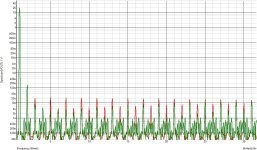
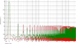
Confirmation of OLG and also FFWD vs TMC with a 100TH inductance in serial with the 47R to keep the same OS Iq.
TMC net is 150 pF + 330pF + 1k, TMC THD is the green FFT, red is FFWD, dont pay attention to H2.
TMC net is 150 pF + 330pF + 1k, TMC THD is the green FFT, red is FFWD, dont pay attention to H2.
Attachments
Love the thread - even if only understand ing 41,8% of it 🙂
//
//

Bridge voltage to feedforward voltage - the running variable is the input voltage of the amplifier

output voltage to ...

output current to ...

current's ...


the same

output voltage to ...
output current to ...
current's ...
the same
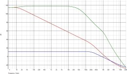
The cut off frequency of the TMC net is a few 10s kHz to just cover the audio band, to extend it upper reduce the 1k
resistance accordingly.
Your THD numbers are apparently measured within a large BW that extend well above the audio band.
Also make sure that the Iq through the 47R is the same, the 100TH indctance is here for this all while
suppressing any FFWD.
resistance accordingly.
Your THD numbers are apparently measured within a large BW that extend well above the audio band.
Also make sure that the Iq through the 47R is the same, the 100TH indctance is here for this all while
suppressing any FFWD.
Don't worry,(...)
I have changed everything exactly as you specified - everything is in perfect order. Iq also ...
#
The simulation results clearly show that the Quad405 works perfectly with its core, and the current dumper principle is also fully confirmed as an error-correcting element.
Unfortunately, wahab's assumptions proved to be incorrect.
Well, then MC12 is obviously lying.Here the comparison at 5.5W, you can see that the TMC cut off frequency is at 35-40kHz with the 1k resistance
and THD in the audio band is lower than with FFWD.
🤣
The beauty of the whole case is that we don't even need a simulator to find out how the circuit works - and whether it works at all. All we need is a pencil, paper, a calculator, a few key figures, a little in-depth knowledge ---> and a few equivalent circuits later, ... we can also quickly add the famous Miller theorem ... and imagination would also be fine.
All can be done without (the need for) a simulator. Current Dumping works, no question about it!
All can be done without (the need for) a simulator. Current Dumping works, no question about it!
As said MC compute the THD within a very large BW, compute it within 200kHz and see what happen.
The 405 enclose the OS within the whole miller loop BW while TMC, as the name suggest, enclose it only on the lower
part of the BW.
Here with the TMC net resistance at 100R, so with the TMC cut off frequency increased by 10x, same colors
as previously, red is FFWD and green TMC, also at 5.5W.
The 405 enclose the OS within the whole miller loop BW while TMC, as the name suggest, enclose it only on the lower
part of the BW.
Here with the TMC net resistance at 100R, so with the TMC cut off frequency increased by 10x, same colors
as previously, red is FFWD and green TMC, also at 5.5W.
Attachments
Last edited:
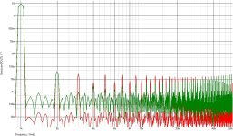
THD1k TMC

no idea what is going wrong (in nowhere),
in any case, the TMC shows instabilities at some points and spontaneous oscillations occur ... Well, this plot shows the enormous potential of this type of compensation-scheme.
But why all this when the QUAD works perfectly and exactly as the manufacturer says it should?
Both methods remain below 2m%.
@wahab
What did you want to prove again? I'm on the tube. Originally you wanted to prove that CD does not work and that there is no error correction in the sense of take away feedforward, but only NFB and GNFB. Correct? Further, that TMC delivers better results than CD and therefore CD would be nonsense?
🤔
Both (concepts) are possible.
It doesnt work the way it is supposed to do, as proved the same amp without FFWD, and without TMC of course,
has the same THD once the OS is biased at a mere 20mA, quite an achievement, the only thing that is relevant
is the very high OLG and hence NFB, wich is the real and only cause of its relatively low THD at the time.
Anyway this design is obsolete for high linearity amps, actualy from the start, with the knowledge accumulated
since 1975 we can do roughly 100x better nowadays without any output coil and still have unconditional stability
on any capacitive load.
THD1k TMC
shows instabilities at some points and spontaneous oscillations occur ...
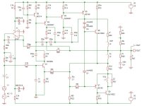
The input transistor has a 1nF cap from base to ground, and a 3.3k in serial with this input.
Normal Operation - Current Dumper - feedforward ...
THD100 with RL=10Ohm

THD1k with RL=10Ohm

THD10k with RL=10Ohm

I think that's data that is impressive. After all, Q7 always has to be switched on first depending on the level. The attenuation factor is exorbitant. So far I have only changed C4 = C3 = 470µF.
THD100 with RL=10Ohm
THD1k with RL=10Ohm
THD10k with RL=10Ohm
I think that's data that is impressive. After all, Q7 always has to be switched on first depending on the level. The attenuation factor is exorbitant. So far I have only changed C4 = C3 = 470µF.
- Home
- Amplifiers
- Solid State
- Current Dumping with OPAMP