They seem to be wonderfull in B+ supply, yeah. Of course can not swapp a good choke quality sound wise.
But again an i/V stages is not a voltage node follower, just poting. Here for instance à strip of diodes for the cathode bias migth not be a good idea... you want linear opération here.
But again an i/V stages is not a voltage node follower, just poting. Here for instance à strip of diodes for the cathode bias migth not be a good idea... you want linear opération here.
Last edited:
I tried SIC diodes as cathode bias and hated them - quite an edgy sound. A bit less edgy combined with a resistor but the resistor alone was better. The idea was to avoid a cathode bypass, but for my taste in music I didn't find SIC diodes usable at all. As you say Iggy, not a good idea. And yes, good chokes in the B+ supply.
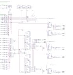
There is the "schematic based reclock" project, which I still have not fully tested 😕
This version is "finished" only for DACs, where standard stop-clock is working without additional BCKs (AD1862, AD1865, ...) - DACs which are latched on LRCK and not BCK. All DACs latched on BCK (PCM63, PCM1702, ...) needs different schematic. You can easily put here some basic schematic and use reclock with it. TDA1540/1 needs also different schematic.
This project needs Quartus 13.1:
https://www.intel.com/content/www/u...design-software-version-13-1-for-windows.html
I tried it in new version of quartus (21), but the schematic based approach is not working good (it is good for VHDL), for schematic based is the best 13.1.
This project is not necessary for the normal functioning of DACs. I don't even know if it will improve the DAC in any way, it's more of an experimental thing. I do not recommend trying this for users who do not know what they are doing, as it may end up with the project not being completed. It will probably be buried here for some student who might later use it in some school work as the basis for something better, he can then share advanced version here 🤣
How the schematic approach in CPLD works, is shortly described here:
https://electrodac.blogspot.com/p/programming-cpld-using-schematic.html
With this "tutorial" you can create own schematic based CPLD for all DACs, where I2S to PCM conversion is needed 😉
Attachments

😍 : thanks miro1360, as usual 🙂
non stop clock option allowed as well for the layout terrorists as I ?
non stop clock option allowed as well for the layout terrorists as I ?
I still think what I said in PM. You migth found a TDA1541A second hand cd player to get the chip, should cost you 30 to 70 pounds if searching . (avoid R1 or non-A ones).I tried SIC diodes as cathode bias and hated them - quite an edgy sound. A bit less edgy combined with a resistor but the resistor alone was better. The idea was to avoid a cathode bypass, but for my taste in music I didn't find SIC diodes usable at all. As you say Iggy, not a good idea. And yes, good chokes in the B+ supply.
It is very personal, alll is compensation when we talk about tones. But at seing many attributes, my personal rank is TDA1541A (alas different pedigrees), ad1862, PCM 56. It is not a verity, it is a trade off when I benchmark them. TDA1541A has... a non "digital" behavior to make it short. But it asks much more effort (so indeed cost a little more at the end than the Total Cost of Ownership winners AD1862, PCM56, AD1865, are). As a jazz drumer you migth prefer though PCM56 or Taiwann made TDA1541A. YMMV.
Last edited:
not a code guy, is it easy to supress the non stop clock behavior from the code, please ? I found one for the sim mode for TDA1541A but not for the second most prefered chip to me that is still AD1862 ? (want to try one day post FGPA/CPLD reclocking due to jitter, starting from a clean MCLK to slave, etc, etc.@diyiggy It is fully open design so you can feed its hunger with any schematic and it will work also as non stop clock option 🤣
I'm a jazz bass player in fact.my personal rank is TDA1541A (alas different pedigrees), ad1862, PCM 56. It is not a verity, it is a trade off when I benchmark them. TDA1541A has... a non "digital" behavior to make it short. But it asks much more effort (so indeed cost a little more at the end than the Total Cost of Ownership winners AD1862, PCM56, AD1865, are). As a jazz drumer you migth prefer though PCM56 or Taiwann made TDA1541A. YMMV.
What pcb did you use for PCM56? I'm trying to find a pcb for the PCM56 but I can't find anything. Just some AliExpress boards with op-amp outputs.
oh my bad.
Met Ferruccio Spinetti ? Seems fun guy ! 🙂
Damit, standfloor bass is hard to make good, if not feasible with an hifi ! and cello even harder !
As I told you it was 20 years I tested the pcm 56. I liked it very much in a clever made made Aiwa cd player I modded on the PS. The output stage of the AIwa used stock some 1:1 coil plus sk170 buffers ! An underated braand imho back then . Very accurate on treble strings.
One guy made a clever pcm 56 dac here if I remember : Bernhard member from Germany, but not cheap to make (needs several pcm 56) and front end migth be better nowadays (which matters a lot for the soud of a dac chip).
Last edited:
Hands up, I surrender. Didn't understand a single word 😂There is the "schematic based reclock" project, which I still have not fully tested 😕
This version is "finished" only for DACs, where standard stop-clock is working without additional BCKs (AD1862, AD1865, ...) - DACs which are latched on LRCK and not BCK. All DACs latched on BCK (PCM63, PCM1702, ...) needs different schematic. You can easily put here some basic schematic and use reclock with it. TDA1540/1 needs also different schematic.
This project needs Quartus 13.1:
https://www.intel.com/content/www/u...design-software-version-13-1-for-windows.html
I tried it in new version of quartus (21), but the schematic based approach is not working good (it is good for VHDL), for schematic based is the best 13.1.
This project is not necessary for the normal functioning of DACs. I don't even know if it will improve the DAC in any way, it's more of an experimental thing. I do not recommend trying this for users who do not know what they are doing, as it may end up with the project not being completed. It will probably be buried here for some student who might later use it in some school work as the basis for something better, he can then share advanced version here 🤣
How the schematic approach in CPLD works, is shortly described here:
https://electrodac.blogspot.com/p/programming-cpld-using-schematic.html
With this "tutorial" you can create own schematic based CPLD for all DACs, where I2S to PCM conversion is needed 😉
Here’s my newest breadboard -
1862 board with JLSounds USB, Miro’s 78xx/79xx PSU, Sowter 1465 I/V.
Sounds great so far!!!

1862 board with JLSounds USB, Miro’s 78xx/79xx PSU, Sowter 1465 I/V.
Sounds great so far!!!
Wow, It uses Ri/v on the secondary... So transforms current pulsesIt doesn't need any buffer behind that transformer?
Hi, I’m using Sowter 1495 with 100R I/V resistor on primary side, but when I connect the transformer with parallel secondary 1:9 configuration, the output is low ( about 400-500mV RMS) when I connect it with serial configuration 1:18 then the frequency response is limited and start to drop at 2kHz.Here’s my newest breadboard -
1862 board with JLSounds USB, Miro’s 78xx/79xx PSU, Sowter 1465 I/V.
Sounds great so far!!!
View attachment 1394808
In your case how big is the I/V resistor and how big is the output (RMS)
Have you measured how the frequency response looks like?
Any suggestions will be appreciated 😀
Attachments

Hi Andy
- 470R grid stopper would be fine
- I'm not too happy with 22K anode resistor, I would want it higher
- 100uF cathode bypass is OK, but my preferred capacitor is DC Link and that would be a big size. Electrolytics will sound worse than DC Link caps. I did a big bypass cap shootout and the only other choice that was nearly as good as DC Links was AudioNote Kaisei in parallel with Elna Silmic II, like 47uF + 47uF or 100uF + 100uF. That's another way to get higher values. But cathode bypass caps are quite audible and have to be chosen with care. So I stay with DC Link caps and use what I have. I have some 70uF ones but they were too tall for the case I used. After that they get expensive as well as big.
- This stage should go into a next stage of minimum 100K input resistor to ground. In that case 0.1uF is enough. Again, the quality of sound of the capacitor comes first. Coupling caps are very audible. I use FT-3 teflon caps. They are again large in size, so 0.22uF would be possible but not much more, and really 0.1uF is enough. Yet again, larger would not fit in the case and I would not use larger caps that were not teflon. I have tried 1uF KBG PIO Russian caps and though they are good they are not as good as FT-3. So I stay with teflon here.
- Yes, a buffer stage would be needed if feeding a solid state preamp, like a cathode follower. It would degrade the sound but it would be a choice. I have a valve stage so 100K input works fine.
- the Riv valie of 125 ohm is for output of 5.5Vp-p (about 2Vrms) wuch is for my opinion to high... The voltage gain of the circuit is about 5.5 Vp-p / 0.25Vp-p, as Io = 2mAp-p for all PCM/AD dacs, so V@Riv and imput to the sircuit is Riv x Io.
-A= 22, (minus is indication for phase shift of 180deg...)
so You can use lower value of Riv. with 47 ohm Riv, and 2mAp-p DAC Io, it will give 2Vp-p at the output with lower THD. which is probably better to use with preamplifier...
- Grid stopper is not critical and can be 100ohm to 1K
- R load is critical in this case because using a high value, decresing anode voltage in the tube, decreasing current and most important setting the tube into non so linear region... That is because of given Vb that could not be higher.
- 100uF cathode resistor bypass C is some minimum value. Negative grid bias could be achieved also with 3 x serial 1.2V batteries without C.
- DC link cap as You called it, first cap following rectifier is critical and should be the same value as other or slight higher. Because of better filtration of AC component. Pleas use PSUD software to see what happening... 22uF is just too low value
- AC load IS critical and 100K is not good idea for this tube because of higher internal resistance, leading to higher output resistance as aprox. Ri II RL. And You will have more than -0,6db loss with 100K as it checked with the spice.
Corresponding Co is also critical. Because of conjuction with Ck and Canode power, and it is responsibile for proper phase.
THis value has to be higher as I calculated bare in mind only one digit phase shift in LF.
But it can be paralleled with this very low 100nF.
- the good tube buffer design will not degenerate sound but opposite. The sound will be beeter with buffer than with a 100K AC load to the circuit. Also device can be more firm to drive capacitive cables.
.
Key points.
Change Rinput of the next stage in preamp to 470K, to maintain loss to -0.12 dbfrom -0.6db
Change C output to 2.2uF minimum for 470K load. Watch out has to be minimum rated as 250V or more
Change CK to minimum 100uF-220uF or 470uF 16V is fine. OR try 3 serial 1.2V batteies of 800mA/h without Ck
Use 22K Rload to match optimum working point with given PSU.
Use first C after rectifier of 100uF
.
Compare the sound with starring values with the same power supply, and I can guarantied that it will be dramatic change in quality
.
About the bleader resistor
I found the for the lower signal values and lower alower consumption, Because Current in R bleader is close to the Tube current. And it is sort of passive shunt to the PS.
The purpose is to dischage the capacitors when power is off. Not to be present oll of the time when device is working.
So the best way is to use some relay to connect bleader in the moment of turning off power suply
In that case device will run without that element and with off state bleder is on and will discharge PS.
Please try simple sound check with and without R bleader connected when device is ON and You will see how the sound is changing - also losing a transparency with bleder is connected...
.
cheers
Last edited:
My plan is: Transformer 1:10, Riv on the secondary and then a tube stage to get about 2VRMS at the output and low output impedance. Since between the DAC and the amplifier I only use a tube buffer with 6N6P without amplification (gain=0.9), I need about 2V RMS at the DAC output. The advantage is that a much smaller Riv can be used if the gain stage is of higher gain (20x or more).Hi, I’m using Sowter 1495 with 100R I/V resistor on primary side, but when I connect the transformer with parallel secondary 1:9 configuration, the output is low ( about 400-500mV RMS) when I connect it with serial configuration 1:18 then the frequency response is limited and start to drop at 2kHz.
In your case how big is the I/V resistor and how big is the output (RMS)
Have you measured how the frequency response looks like?
Any suggestions will be appreciated 😀
Another (cheaper) option is only Riv (100ohm or less for AD1862, 50ohm or less for PCM63) and then tube stage with higher amplification, (at least 30x) like a Mu follower or classic solution with common cathode gain stage and cathode follower.
The third option is whatever comes to my mind that is good and contains tubes. 😁
Last edited:
Previously I had 6DJ8 tube stage in SRPP configuration with gain 20x. Since the transformer in 1:18 configuration is similar, I tried to use only the transformer. That was a mistake, tube stage sounded much better. I tried to put I/V resistor to secondary side, to primary side, it doesn’t helped to improve the sound quality.
My plan is to test Nelson Pass’s DIY Front End, and use it after the parallel transformer configuration, and set the gain 6-8x to get 2V
Or put back the tube stage, but it is not ideal, since SRPP highly dependent on the load.
My plan is to test Nelson Pass’s DIY Front End, and use it after the parallel transformer configuration, and set the gain 6-8x to get 2V
Or put back the tube stage, but it is not ideal, since SRPP highly dependent on the load.
Well, you never know with those transformers. They are expensive, and usually the result is known only when you hear it. I will go for custom transformers on mumetal cores. I have good cores for that (already tried with AD1862 and PCM63), and it won't cost me much. First, only Riv and then tubes will be tried, because it is simpler. After that, there will be experiments with transformers, so what gets better stays.
When I was experimenting with DDDAC and output transformers, I tried probably 10 pieces until I found the best sounding one. The same one, only with a different configuration, will also work here I guess. What I know for sure after everything I tried with transformers, without an oscilloscope and a function generator, it is practically impossible to set it up properly.
Try turning SRPP into a Mu follower, it might be better. You will also get a little more gain, about 30x with 6DJ8. That tube is not favorable for SRPP, the cathode-heater breakdown voltage is low (Vkf=50V).
Last edited:
This model 1945 has main issue of too low primary inductance acording to datas it is 0.72 Hy per each primary coil...Hi, I’m using Sowter 1495 with 100R I/V resistor on primary side, but when I connect the transformer with parallel secondary 1:9 configuration, the output is low ( about 400-500mV RMS) when I connect it with serial configuration 1:18 then the frequency response is limited and start to drop at 2kHz.
In your case how big is the I/V resistor and how big is the output (RMS)
Have you measured how the frequency response looks like?
And obviously higher capacitances causing loss in HF...
.
A lot better model is 1645 with 3 Hy eah coil but almost the same Rdc as Your 1945 model.
there are some simple measurements that confirming differences about L primary
https://www.bramjacobse.nl/wordpress/?p=6233
When connected like this, DAc Iout is directly and heavily loaded with huge reactances. From primry and additionaly from transfered secondary side. And losses will be huge. Also it is useful to simulate this configuration against Riv first at primary and compare results...My plan is: Transformer 1:10, Riv on the secondary
.
When Riv is at the output of DAc Io, we also have reactive load componenet as parallel complex componenet but in parallel with lower value of Riv. (In that case it is almost irrelevant internal reactive component, non-inductive etc, of the Riv because a much larger are already present from the succeeding transformer...)
.
All in all the best way for using a non reactive Riv is
to aply non-rective very low inductance and very low capacitance R @ DAC Iout
then go to low output impedance buffer to isolate ractive component from DAC Ioutput (in that case we have only few pF and no dynamic capacirtance at the DAC output, so rective component is completly minimized.
after thet connect the transformer. Thansformer will have prppper low impedance drive, LF chrs will be much better, THD will better and HF will better too...
then measure with square wave, and RC terminate secondary for riging, use higher termination load.
The another buffer with separate PS after the secondary is na option, this time to mimize influence of the capacitive load to the secondary...
This way DAC as DA system is compleatly galvanicaly isolated from pure Analog domain. As main feature of transformer as isolation element...
🙂
- Home
- Source & Line
- Digital Line Level
- DAC AD1862: Almost THT, I2S input, NOS, R-2R