V R2 = V R3 approx 10.9V to 10.95VNo. Disappointed with the product package and support. I feel like a testing scheme -- which is promised but missing in the product listing -- is essential to a complete product. Without it I feel shortchanged by DIY Audio.
V R5 = V R6 approx 10.9V to 10.95V
V R4 = 1.25V
V R15 = approx 4.5V (my value is around 4.6V measured on the board)
Hope this is helpful.
Last edited:

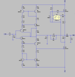
Would this be a valid scenario? I need for my balanced ACP 2 voltages 5V and 12V. I am using IRM03-05 and IRM02-12 Meanwell modules but they are pretty noisy 😵 High frequency pitch.
So I designed this but don't know if there are downfalls for this scenario, bij adding two rectified voltages to a higher voltage.
When testing the 5V 250mA is stable. but when I load the 12V with 50mA, the 5V decreases to 4.5 V. When measuring I have only 6.9V as input for the 7805 which is too low I guess. So maybe use a LDO regulator? Or is it this design what sucks 😉
Hope you can help.
View attachment 1363293
I haven’t studied what you are trying to achieve, so these comments may not be helpful.
Why is pin 1 on D2 connected to pin 4 on D3?
Get a 50VA transformer. Transformer seems under rated.
Last edited:
yeah, you did not study my question and intentions enough 🙂
I'm trying to achieve 2 voltages from 1 transformer with 2 windings. Thats why I connect pin 1 to pin 4, to sum up the both rectified voltages. It is not for an ACP+ PSU but to replace two Meanwell IRM-03-5 and IRM-02-12 switching supplies. Which I use for the controller board with Arduino of my ACP balanced.
I'm trying to achieve 2 voltages from 1 transformer with 2 windings. Thats why I connect pin 1 to pin 4, to sum up the both rectified voltages. It is not for an ACP+ PSU but to replace two Meanwell IRM-03-5 and IRM-02-12 switching supplies. Which I use for the controller board with Arduino of my ACP balanced.
But I finished my new ACP+ balanced, if you see the pictures you will know what I meant. Will post later today.
These two Meanwell switching PSU's i try to replace with a conventional PSU. Because those Meanwells are making a high pitch sound in the air all the time.

My Mod to ACP+ Headphone amp based on LTSPICE Simulation File by @EUVL.
JFET LTP Input stage replaced with Diamond Current Feedback Input stage.
Harmonic Frequency Fourier Normalized Phase Normalized
Number [Hz] Component Component [degree] Phase [deg]
1 1.000e+03 4.662e-04 1.000e+00 0.67° 0.00°
2 2.000e+03 9.898e-08 2.123e-04 -85.73° -86.40°
3 3.000e+03 9.001e-08 1.931e-04 -80.84° -81.52°
4 4.000e+03 5.325e-08 1.142e-04 158.00° 157.33°
5 5.000e+03 6.426e-08 1.378e-04 164.43° 163.76°
6 6.000e+03 1.370e-07 2.938e-04 -43.29° -43.96°
7 7.000e+03 3.803e-08 8.156e-05 -90.04° -90.72°
8 8.000e+03 1.943e-08 4.167e-05 -153.60° -154.27°
9 9.000e+03 9.522e-08 2.042e-04 -44.36° -45.03°
Total Harmonic Distortion: 0.050081%(0.087311%)
Might Need a DC Servo, please check it before building
Attachments
An update with my ACP+ with FlexReg...
I was having an unrelated chat over in the F5M thread, in which @ItsAllInMyHead was educating me on kinds of ground lifts, mentioning that they can be thermistors, or maybe bridge rectifiers that don't appear related to AC to DC duties.
"I feel like I've seen that somewhere before...", I thought absently before laying down for a nap.
20 minutes later...
"WAIT A MINUTE!" Bam, I sat straight up in bed.
Here's the FlexReg Single Rail circuit:

There it is, over the right - a ground lift that goes to the 'CHASSIS_GROUND' header. Turns out I ran this to the chassis (correct), but, not understanding this was labelled as Chassis Ground because it was lifted, I then also ran the ACP+ board direct to the chassis, effectively bypassing the ground lift through the ACP board. I realised that the ACP+ board doesn't need to go to the chassis, because it is connected to GND_1 on the FlexReg already.
Anyway, I've removed that erroneous connection, and I'll give it a bit of a test in the next few days, but initial impressions are that all is well. 🙂
I was having an unrelated chat over in the F5M thread, in which @ItsAllInMyHead was educating me on kinds of ground lifts, mentioning that they can be thermistors, or maybe bridge rectifiers that don't appear related to AC to DC duties.
"I feel like I've seen that somewhere before...", I thought absently before laying down for a nap.
20 minutes later...
"WAIT A MINUTE!" Bam, I sat straight up in bed.
Here's the FlexReg Single Rail circuit:
There it is, over the right - a ground lift that goes to the 'CHASSIS_GROUND' header. Turns out I ran this to the chassis (correct), but, not understanding this was labelled as Chassis Ground because it was lifted, I then also ran the ACP+ board direct to the chassis, effectively bypassing the ground lift through the ACP board. I realised that the ACP+ board doesn't need to go to the chassis, because it is connected to GND_1 on the FlexReg already.
Anyway, I've removed that erroneous connection, and I'll give it a bit of a test in the next few days, but initial impressions are that all is well. 🙂
Ground lift may be omitted if direct connection is not noisy. I have done that with my DIY FE 2022 preamp.
Finally done 😛
My ACP+ Balanced preamp.
I made a version 2, in a Modushop Slimline 2U enclosure, with all the Digital Control part with Arduino on a separate print on the frontpanel. So no more small PCB's and connection wires.
Also we developed a new Volume Relais control board ourself, where my colleague Peter did all the software. The ACP+ has a buffer B1 R2 in it, in case you need no gain.
You can switch to it with 'direct-out'.
As remote we use the nice AppleTV remote controller.
Transformer is a Toroidy 120VA 🙂 The whole amp gets bloody hot, it uses around 30-40VA, the perforated Slimline cover is needed.
Here are some pics.
I will post more porn in the Pictures of your diy Pass amplifier thread. Hope you like it...
Thanks for Modushop and Gianluca, doing the incredible customizations of the frontpanel 👍


Walter, this is very nice as always.
Could you describe the difference in sound character between ACP+ and B1 r2 in a few words?
Could you describe the difference in sound character between ACP+ and B1 r2 in a few words?
@WalterW Very nice, and thanks for confirming that a Toroidy transformer with their mounting plate will fit in a 2U enclosure. I am using one about the same size (100VA) for a UGS Muse preamp and was worried it might be too tall. Did you use 10mm standoffs, or something shorter? Also, did you make your own pushbuttons or did you find them somewhere?
- Home
- Amplifiers
- Pass Labs
- Amp Camp Pre+Headphone Amp - ACP+