Anyway, my question is related to temperature. My garage was a cool (but relatively consistent) 10C while all this testing was going on, which is likely significantly cooler than the inside of an ACP+ (I plan to put it in a chassis). Do I need to test again at a more sensible temp somehow, or am I going to be well within the ballpark as is? What's more important - hitting exactly 10mA, or a tight J113 match?
Temperature does make a difference. You may need more resistance at a higher ambient temperature.
A tight match will mean closer match between channels using the same value resistor.
As for the 10mA current, that will depend on the voltage at test point DC1 on the ACP+ board. According to Nelson, the goal is 11V plus or minus 1V. I suggest starting out with 10mA and checking the DC1 voltage, and only adjust the current if the DC1 voltage is not within Nelson's recommendation.
Thanks for that, Ben. It's interesting because on the bench it seemed that the relationship was the other way - higher temp lowered IDSS, meaning less resistance than when cold to hit the 10mA mark. But I have not measured the temps to confirm, and wouldn't be surprised if I am getting it muddled. I'll wait for a warmer day and test again - I am waiting on more parts anyway so no rush.Temperature does make a difference. You may need more resistance at a higher ambient temperature.
A tight match will mean closer match between channels using the same value resistor.
So, to see if I'm understanding correctly:
- literally any J113 that can hit 10mA with an appropriate value resistor will do, even if the IDSS and resistance values are quite different between sides
- matching IDSS makes resistor selection simpler, but isn't required
- if anything, you want IDSS values at the specified voltage that can hit 10mA with a common value (100ohms being easier to find than 84.7ohms or something)
I have to say, it has been fun to match them anyway. Something satisfying about hitting the number bang on. It has also been fun to learn how. I actually have a pair that match beyond my DMM's digits (so less than 0.005mA difference). I'll see how they do at a higher ambient temp and buy a few odd value resistors around the ideal resistance.
As for the 10mA current, that will depend on the voltage at test point DC1 on the ACP+ board. According to Nelson, the goal is 11V plus or minus 1V. I suggest starting out with 10mA and checking the DC1 voltage, and only adjust the current if the DC1 voltage is not within Nelson's recommendation.
Ah, so solder and see. Makes me wonder if I should set up the FlexReg board with the variable regulator so if the voltage is out of spec at DC1 I can just dial it at the source and avoid desoldering anything. 😂
I just looked at the J113 spec sheet and the temperature effect is not so simple. So it may be as you observed and not as I assumed.
In this application the J113 is a constant current source (CCS) for the two J74. So yes, any J113 with the appropriate resistor that gives 10mA of current will do.
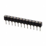
If you want adjustability, the simplest way to achieve that is to put pin sockets at the J113 resistor locations on the board so that resistors may be placed without soldering. Once the final resistor value is determined the resistor can then be soldered to the pin socket.
Attachments
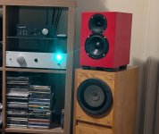
I have recently completed building the ACA Mini. It's driving a pair of Bipole microTowers outfitted with Mark Audio Pluvia 7.2 HD drivers. It sounds fantastic. I picked up the new Schiit Saga 2 as a preamp to audition, and the sound is great. I can't help to wonder if the ACP+ may actually be a better fit as strictly a preamp - no intent to use headphones.
Thoughts from folks who run the ACP+ to ACA Mini?
Thoughts from folks who run the ACP+ to ACA Mini?
Last edited:
Up until a few months ago I ran the amp camp pre into the amp camp mini to drive a pair of 98db sensitive horn speakers. It's a great match.
It would get run with the jumpers installed on the amp camp mini as the preamp added 2nd order harmonics and it seemed to be too much when the amp was doing it too.
Oddly, the 2nd order from the preamp was somehow different than the 2nd order from the amp. Can't explain it but preferred the amp with the jumpers in place even with a preamp that doesn't add 2nd harmonics.
The amp camp mini sounds great with the B1 Korg preamp, too. And it's good with the Whammy but it doesn't seem to add any 2nd order magic.
If the amp camp mini drives your speakers well and you like 2nd order harmonics then adding the ACP should be a good fit.
My $0.02
It's an excellent combination and I'm not even going to say for the money, It's just sounds good-- really, really good-- irrespective of its cost.Thoughts from folks who run the ACP+ to ACA Mini?
Yes, for sure. My preference, though, is the ACP+ to Mini. And like you, with jumpers in.The amp camp mini sounds great with the B1 Korg preamp, too.
Built the Amp Camp Pre-amp HPA+ which died after two days. I need the schematic with test points and test data to debug. Can anyone point me to this? Thank you.
https://guides.diyaudio.com/c/AmplifiersBuilt the Amp Camp Pre-amp HPA+ which died after two days. I need the schematic with test points and test data to debug. Can anyone point me to this? Thank you.
I used the build guide but as it says, the testing procedures are under development. I had hoped this omission had been addressed but perhaps not.
Welp, the smoke stayed in, so that's a win.
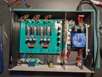
It's not quite as neat a job as I had hoped - I hate soldering wires to boards, so why I chose this way to build it is a mystery - but things seem to check out. 24.08V supply, a bit high at R18 with .378V, but 10.75V and 10.78V for DC1 and pretty much bang on 10mA per R4 (95.3ohms per side and 0.958Vand 0.954V respectively).
Mainly this gives me a bit of confidence heading into an F5M build down the line.
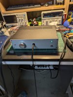
ACP+ w/FlexReg


Very nicely done!!
🙂 🙂 🙂
It was your work that inspired this build, actually, so thank you. 😎
Only took me 2 years to get on with it. 😂
Looks very nice! That is a tight fit lengthwise for the ACP+ and Flexreg PCBs, so very good machining.
Looks very nice! That is a tight fit lengthwise for the ACP+ and Flexreg PCBs, so very good machining.
Thank you, but it's all smoke and mirrors. 😅 I oversized the holes in the baseplate for the M3 (insulated) standoffs to allow sufficient wiggle room and compensate for inevitable line up issues. I have a punch and a drill press and still can't seem to achieve precision greater than 0.8mm or so. Practice, maybe.
I am happy with the power supply shielding though - I bought a 1.5mm sheet of gal steel and took to it with an angle grinder and cutting disc. First time using an angle grinder - a very satisfying tool. I felt like a proper mad scientist with the eye protection and the sparks flying. 😂
This modern day LEDs are so bright, I use a 47K resistor for them....
I absolutely should've done that - I underspecced it because I was initially going to use a much dimmer one, but then I couldn't find it in my stash and ordered this instead. Lesson learned - you could put on a shadow puppet show with this thing at the moment. 😂
"Measure twice, cut once" translated into electronics. "Choose an acceptable LED brightness (get your spouse's approval too) before calculating its current limiting resistor value".
Futz around on the test bench with milliammeter, variable DC supply, 10K resistor, and LED. Dial up and down until "perfection" is reached, get approval, write down LED current in your lab notebook, done.
Futz around on the test bench with milliammeter, variable DC supply, 10K resistor, and LED. Dial up and down until "perfection" is reached, get approval, write down LED current in your lab notebook, done.
Would this be a valid scenario? I need for my balanced ACP 2 voltages 5V and 12V. I am using IRM03-05 and IRM02-12 Meanwell modules but they are pretty noisy 😵 High frequency pitch.
So I designed this but don't know if there are downfalls for this scenario, bij adding two rectified voltages to a higher voltage.
When testing the 5V 250mA is stable. but when I load the 12V with 50mA, the 5V decreases to 4.5 V. When measuring I have only 6.9V as input for the 7805 which is too low I guess. So maybe use a LDO regulator? Or is it this design what sucks 😉
Hope you can help.
- Home
- Amplifiers
- Pass Labs
- Amp Camp Pre+Headphone Amp - ACP+

