This lack of dimensional information exists for most of the PCBs here. If not in the store listing, then the dimensions of each PCB should be listed in the BOM or guide. Perhaps we can just start a thread with a single page listing zpCB dimensions.
"Measure twice, cut once" translated into electronics. "Choose an acceptable LED brightness (get your spouse's approval too) before calculating its current limiting resistor value".
Futz around on the test bench with milliammeter, variable DC supply, 10K resistor, and LED. Dial up and down until "perfection" is reached, get approval, write down LED current in your lab notebook, done.
I don't have much of a head for millicandela ratings yet, so I'll definitely do that kind of preliminary testing from now on. I vastly underestimated this particular LED - see below the now reasonable brightness, achieved with a total of 85.5Kohms. Not a figure many people would've had on their dropper resistor bingo card.

This lack of dimensional information exists for most of the PCBs here. If not in the store listing, then the dimensions of each PCB should be listed in the BOM or guide. Perhaps we can just start a thread with a single page listing zpCB dimensions.
I feel like this information used to exist on the page but got lost in the website update? I know I grabbed dimensions from the site somewhere before I had the boards in hand. I agree that it needs to be a part of the product information.
Last edited:
Sigh.
So, the sound of my ACP+ with headphones is quite peaky - clean, but the treble seems elevated. I've read enough build posts to know this might be a sign of oscillation, but I don't quite know enough to know how to test for it, or what to do to fix it if I find it.
I have a scope, but no function generator.
Is someone able to point me at a guide or resource? Thanks in advance.
If you've a scope you can look at the output for oscillation... make sure there's nothing happening at frequencies outside the audio band.
Also, you do have a function generator if you have a smartphone or iPad. Lots of apps out there for that kind of thing.
Thanks for that, I'll look into it. Might have to teach myself more about this scope.
Also worth mentioning, the low-hanging fruit in possible oscillation is proper chassis bonding + grounding and making sure the metal front of the potentiometer is well-grounded. It seems like it might be not related, but trust me, it's common, particularly on fly-wired pots.
Make 100% sure all 6 panels of the chassis are electrically connected to each other, this always requires sanding and scraping of anodization on parts that can bond to each other, and then make sure the grey metal front of the pot is also well connected electrically to the chassis front panel.
Take a look at steps 31-37 of the Pearl 3 guide and see just how much scraping I did on that chassis to make sure it was electrically connected. https://guides.diyaudio.com/Guide/Pearl+3/28?lang=en In this example it was specifically for noise performance, but it also helps with oscillation.
Also worth mentioning, the low-hanging fruit in possible oscillation is proper chassis bonding + grounding and making sure the metal front of the potentiometer is well-grounded. It seems like it might be not related, but trust me, it's common, particularly on fly-wired pots.
Make 100% sure all 6 panels of the chassis are electrically connected to each other, this always requires sanding and scraping of anodization on parts that can bond to each other, and then make sure the grey metal front of the pot is also well connected electrically to the chassis front panel.
Take a look at steps 31-37 of the Pearl 3 guide and see just how much scraping I did on that chassis to make sure it was electrically connected. https://guides.diyaudio.com/Guide/Pearl+3/28?lang=en In this example it was specifically for noise performance, but it also helps with oscillation.
Thanks again, @6L6 . I'll check the pot later tonight - I'm 100% confident all the panels have continuity to ground as I removed a healthy amount of anodising and paint around all the contact points (more than in the Pearl guide - I used an engraving pen and left no paint or anodising at all in within the radius), used shakeproof washers wherever possible, torqued the hell out of them so they bit down hard, and tested everything to everything else with a DMM and got 0 ohms from every panel to every other panel. The pot escaped my attention, however. I'll be very happy if I can get a win that easily!
Well done for the attention the panels! Looking closer at your photos I do see it now. Nice.
Thank you. I'm keen to check with a scope to confirm there is something going on, but I've not done it before. I'm pretty worried about connecting the ground leads in the wrong place and blowing things up. Is there a standard procedure for how to probe the outputs?
No easy answers today. Just checked the pot. Zero ohms from the metal face to the chassis and the earth pin.
Here's a photo of the kind of thing I did with the chassis grounding using the engraving pen, FWIW:

There are only 3 other things I did that might be effecting things:
The other thing I vaguely remember, the 4 MOSFETs I used, when I tested them with my DCA 75 Pro, had Id/Vds curves that were very closely matched, but were significantly different to those I measured from a later batch of 10 I ordered as backup. The 4 used had quite a steep curve, vs the later 10, which took longer to top out. Not knowing much about MOSFET behaviour, I shrugged and went with the steep curve ones because they were most alike.
Here's a photo of the kind of thing I did with the chassis grounding using the engraving pen, FWIW:

There are only 3 other things I did that might be effecting things:
- I soldered 1Mohm resistors across the input RCAs to suppress pops etc. if a lead accidentally gets yanked (I did this on my Whammy and it worked well there).
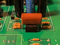
- I replaced the 10uF electrolytic C1 caps with 4.7uF Panasonic PP film caps, which in itself isn't a strange mod, but I took an unconventional approach to mounting them to keep the leads short and avoid glue etc. Basically the C1 leads go into the inner R1 and R3 pads, and R1 and R3 are soldered to the legs of C1 like guy wires. I stared long and hard at the PCB and the schematic, and was convinced that this was electrically identical to the standard configuration (Input > R1 > C1 > R2, R3, & Q1) and just moves the fork in the road slightly, but if anyone can give me a good reason why it's the likely culprit I'll reverse it. What I don't want to do is reverse it just because it's odd, and find that it's not the issue. I would sooner eliminate other possibilities first. One member did say not to do it when I asked a while back, but did not give a reason to do with the circuit - they seemed to be saying it was bad for reasons of durability (which I was/am okay with).

- The shielded CAT 5 I used on the input switch wiring has a drain wire connected on the board side only to one of the unused ground plane vias on the pcb. It is not connected on the switch side.
The other thing I vaguely remember, the 4 MOSFETs I used, when I tested them with my DCA 75 Pro, had Id/Vds curves that were very closely matched, but were significantly different to those I measured from a later batch of 10 I ordered as backup. The 4 used had quite a steep curve, vs the later 10, which took longer to top out. Not knowing much about MOSFET behaviour, I shrugged and went with the steep curve ones because they were most alike.
Did you have success troubleshooting this issues?Built the Amp Camp Pre-amp HPA+ which died after two days. I need the schematic with test points and test data to debug. Can anyone point me to this? Thank you.
Anyone know why the store put in huge 150k resistors that won’t fit the lead spacing on the board?
I want to, but I'm very new to scopes (I only bought mine recently to do the Quasimodo snubber thing) and I need to find a good explainer of what to do. I don't want to just dive in there because what little I do know is:Have you identified that you definitely have oscillation with a scope yet?
1) this ACP+ has earth ground
2) earth ground and signal ground are not the same thing
3) put the probe's ground clip in the wrong place and KABLOOEY
I would like to avoid kablooey.
No. Disappointed with the product package and support. I feel like a testing scheme -- which is promised but missing in the product listing -- is essential to a complete product. Without it I feel shortchanged by DIY Audio.
If you go to the diyAudio Store page for the ACP+, Nelson's article on the ACP+ can be accessed from there. The article includes a schematic and other information.
Here is Nelson's article:
https://www.firstwatt.com/wp-content/uploads/2023/12/art_acp.pdf
If you need help troubleshooting your build, post information here and diyAudio members will do their best to help you get your ACP+ working again.
Here is Nelson's article:
https://www.firstwatt.com/wp-content/uploads/2023/12/art_acp.pdf
If you need help troubleshooting your build, post information here and diyAudio members will do their best to help you get your ACP+ working again.
- Home
- Amplifiers
- Pass Labs
- Amp Camp Pre+Headphone Amp - ACP+
