Hanseat - a North German quick idea
It is not an MF-A1 and yet it tries to break all records with a real 14 watts. This is due not only to its EF push-pull power amplifier, but also to its unusual operating point setting. This glider should not be missing in any child's room.
HBt.
It is not an MF-A1 and yet it tries to break all records with a real 14 watts. This is due not only to its EF push-pull power amplifier, but also to its unusual operating point setting. This glider should not be missing in any child's room.
HBt.
Attachments
Last edited by a moderator:

namely the 0.47R resistances that heavily compromise the output Z.
Basically, this situation has bothered me for decades. Of course, there are many possible solutions - but when you look at it closely, a series resistance of 1/2 ohm is only extremely rarely of negative significance.
A device similar to an A1 rarely has to drive and electrically control a woofer with a Qtc of greater than 1/sqrt(2) and a DC coil resistance of 4 to 2 ohms. It is not a PA subwoofer but a hi-fi amp.
0.5 Ohm certainly represent the upper, tolerable value.
Hanseat,
the nephew of the legendary MF-A1.
Doesn't the MF-A1 separate the DC/bias feedback from the AC feedback? Use that scheme to address the objections regarding the output Z.
Or perhaps I'm thinking of one of the variations that have appeared recently. No matter: there are ways.
Or perhaps I'm thinking of one of the variations that have appeared recently. No matter: there are ways.
Doesn't the MF-A1 separate the DC/bias feedback from the AC feedback?
No,
the design of the MF-A1 does not separate the two control circuits (ac & dc) from each other. The A1 only creates a DC voltage offset, which is defined as far as possible, but nothing more!
Even if an A1 sounds very good and is charming, it is by no means a masterpiece of engineering. For me personally, an A1 is a piece of handicraft work on the kitchen table, depending on your perspective. Like everything in life, there are two sides to a coin.
The Hanseat is my quick tinkering offer.
HBt.
A1 some meaningful modifications
we should lead by example in the aforementioned thread. At some point, I won't be sitting in the penalty box either.
we should lead by example in the aforementioned thread. At some point, I won't be sitting in the penalty box either.
The lower (or upper half, the 3/4 😉) half /branch of the circuit alone represents a quasi short circuit, or rather connects its open collector (practically) via the Rsense=0.47Ohm to virtual 0V, quasi ground. Now it comes to the current flow, the Iq.The A1 only creates a DC voltage offset, which is defined as far as possible, but nothing more!
tpc
My assertion is based on the following:No,
the design of the MF-A1 does not separate the two control circuits (ac & dc) from each other. The A1 only creates a DC voltage offset, which is defined as far as possible, but nothing more!
Even if an A1 sounds very good and is charming, it is by no means a masterpiece of engineering. For me personally, an A1 is a piece of handicraft work on the kitchen table, depending on your perspective. Like everything in life, there are two sides to a coin.
The Hanseat is my quick tinkering offer.
HBt.
The DC feedback loop is lowpass-filtered and its CLG is very close to 1 @dc. It is an "interesting" signal path because it acts to both set the outputs' idle current and performs some correction for the average output offset voltage. The highpass AC feedback loop, which determines the amplifier's signal gain, is AC coupled and has much higher gain. It has nothing to say about the idle current or average output voltage offset.
Different functions, fundamentally different behaviors. Perhaps we just have a different set of words to describe the same situation, and I'm good with that 🙂.
Your Hanseat design is an elegant way to address some of the A1's shortcomings. It will be interesting to see where that goes.
and other languages: in native language and of course /maybe technology,Perhaps we just have a different set of words to describe the same situation, (...)
no problem
😉
!
greetings,
HBt.
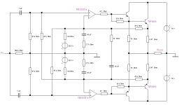
Below schematic copied from post 2.
How could a single feedback node from the output possibly satisfy two different opamps? Strikes me untested, unworkable.

How could a single feedback node from the output possibly satisfy two different opamps? Strikes me untested, unworkable.
In simulations it worked on the first try without changing anything, THD residuals are below -106dB/15V pk/8R,
and of course dissipation is huge at roughly 50W since that s class A.
and of course dissipation is huge at roughly 50W since that s class A.
Re post 2 and 10 I think it works, but not extremely well.
Both opamps operate in parallel more or less, but it should
be investigated what happens if their offset is far off or with
input of high frequencies. Compensation may be in error.
This diamond output can be driven with a single op amp.
Both opamps operate in parallel more or less, but it should
be investigated what happens if their offset is far off or with
input of high frequencies. Compensation may be in error.
This diamond output can be driven with a single op amp.
And yet we see successful implementations of fully-symmetrical amplifiers using an NPN-based differential pair for one side and a PNP-based differential pair on the other, used with very good results when used in a well-designed circuit.
This is not to say that there is some inevitable disagreement between the two halves, but it is minimized by the separate feedback loops. They have the SAME input signal and sufficient open-loop gain to keep the disagreement to a minimum. I note that among the variations on the A1, the ones with higher OLG perform better in terms of THD: and, just perhaps, there is more than ONE reason for that.
One "fly in the ointment" could the gain mismatch in the two halve's CLG -- but the A1's CLG is set by just ONE voltage divider. Non-issue. Hehe.
I may be starting to sound a bit like @hbtaudio here. But it likely is just a temporary thing 🙂.
Post 1 : how do you want to implement the bias voltages ?
|10.5V| practically represent a |10.5µA| current source due to the very high series resistance of 1Meg Ohm. The node of the inverting input should be set with regard to the offset currents ...
So how?
Actually quite simple, the main thing is it must be adjustable ..! Honestly, I don't know yet, or I don't want to have to specify it (yet).
Pre-chewed food is not a tasty menu.
🤐
- Home
- Amplifiers
- Solid State
- "Der Hanseat" - the answer to all class A questions!