Or be transformed into a fantastic KRILL.This diamond output can be driven with a single op amp.
Perhaps wahab can discuss the circuit from posting #2 in a separate thread - I myself have no interest in this external circuit.
HBt.
Let's think together about the implementation of the 10.5µA source or sinks.
My thoughts are already spraying 🎇.
My thoughts are already spraying 🎇.
A very quick thought about one possible realization of the adjustable positive reference voltage!
Will this MF A1 threads and various subthreads continue in 2025? Please start a everythingaboutMFA1.com forum website then.
Don't panic,Will this MF A1 threads and various subthreads continue in 2025? Please start a DIYMFA1.de forum website then.
I'm happy to keep my mouth closed forever - if that's what you want.
☕
Dear Jean-Paul,
don't you like the MF-A1 amplifier?
regards,
HBt.
That is not what I want. It is just that the impression is that you are mainly talking to yourself. Also OK but less interesting to readers and participants maybe.
What I think of the stove is not at all important. It is history. Thankfully.
What I think of the stove is not at all important. It is history. Thankfully.
I have to agree with you, I've had this impression all my life. What would be an interesting topic that also captivates you? Class D maybe ...That is not what I want. It is just that the impression is that you are talking to yourself.
Anything varied. Not just 1 device in various incarnations as it all boils down to 1 subject then.
I understand that very well. And of course you're absolutely right - we regularly reinvent the wheel. Finding a truly new technology, a magical and completely unknown form of circuitry - that will be difficult.Anything varied. Not just 1 device in various incarnations as it all boils down to 1 subject then.
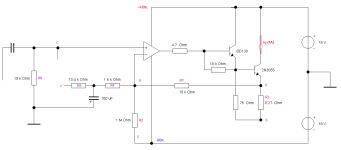
I'm sorry to throw cold water, but feel compelled to comment. I think Paravincini's bias scheme was an intriguing idea, but perhaps has intractable problems. I paste the schematic from the OP for discussion convenience.
Other members have noted the importance of having perfectly matched upper and lower halves. Let's posit that is the case and that there's prefect symmetry--- ideal devices, that standing bias works well, all resistors and caps are perfectly matched. Everything is fine until the amp leaves class A and enters B.
Note that top and bottom both have equal AC gains at the output emitters, so in class A, each emitter accurately drives its 0.47R and thus the amp has an output resistance of 0.47R/2 = 0.235R. It will have a damping factor 8/0.235 = ~34. Not huge, but OK. But when class B begins in the positive output transistor, the voltage gain at the NPN emitter remains unchanged, the PNP turns off, and the amp driving impedance rises to 0.47R. There's no global feedback directly from the speaker, so the abrupt change in driving impedance generates distortion. It appears to me that this issue is inescapable if the amp operates in class AB.
Am I missing something? Thanks.

You haven't overlooked anything, your analysis is correct.
The idea of the offset controlled bias Iq is interesting and works perfectly up to a certain point. I deliberately leave this point undefined in the room, you don't always have to reveal everything straight away. The fact is, as long as the amplifier remains in A mode, everything is fine.
What is important in the analysis is the static view and the dynamic view, the dynamic view includes a typical equivalent circuit diagram of the entire amplifier ... Unfortunately, the range of validity is very narrow, and we must also pay special attention to the steady state and the transient state.
Under no circumstances do I want to complicate the matter, we have tools such as MC12 and all other PSPICE-based simulators, with their help you can check or internalize a lot before a test build. Some things are even much simpler and more sensible than getting to the bottom of things with a test setup.
#
The idea of the Hanseatic is definitely very exciting.
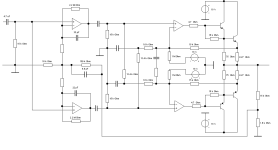
I have been working on a variation of the A1, to explore its use as a headphone amplifier. It turns out it wasn't too difficult to modify it so it resembles the subject of this thread...

Using EF outputs rather than the A1-style of common emitters greatly simplified the compensation requirements to achieve stability. As in, none was needed (pretty nice after tearing my hair out over some other versions!). However, as drawn the AC response does show a ~3dB peak at 3MHz 😉. Adding a 10pF capacitor across the 5K feedback resistor addressed that.
Based on my experience with one of the JLH HA designs, the capacitor may not be needed in a real-world implementation.
I'm not in any way suggesting this as an alternative, just showing that it appears to be a fairly robust topology. At least in simulation.
It would be instructive to examine its distortion vs. transistor mismatch. I suspect it's low since all the voltage gain is in the opamps.
BTW, in this simulation the outputs are in pure class A mode. Peak current is about 8mA, and the idle current is 100mA.
The beauty is:
We use an operational amplifier and assume it to be ideal; at the same time, the entire circuit works with a stabilized or regulated power supply unit.
What remains is an absolutely rebuildable ( profane op-amplifier- ) basic circuit. We do not need any extra reference voltages or current sources ...
12 to 14 real Class A watts - and these will definitely put a JLH-69 in your pocket.
Attachments
Last edited:
I have to agree with you, but this unnecessary debate has already been held - unfortunately with no good end, there was a lack of will to understand /insight.I fail to see what the circuit in post 1 has to do with the Musical Fidelity A1.
Why compare apples with a phantasy exercise ?
Of course, the Hanseat is an illustrative exercise, it extends the power range of an operational amplifier by an emitter follower and sets a defined offset that is different from zero.
That's all it is,
but it's very practical and fully functional.
Greetings,
HBt.
The crazy thing
We could also use any commercially available power operational amplifier without the additional EF.
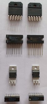
For example:
LM3886, TDA1514 or TDA2030, TDA2050 - a TCA2465 is also sufficient for headphones.
In addition,
we can give free rein to our play instinct, isn't that wonderful - we could build amplifiers with our children or grandchildren!
We could also use any commercially available power operational amplifier without the additional EF.
For example:
LM3886, TDA1514 or TDA2030, TDA2050 - a TCA2465 is also sufficient for headphones.
In addition,
we can give free rein to our play instinct, isn't that wonderful - we could build amplifiers with our children or grandchildren!
Attachments
Here's a little problem --

This simulation shows the result of one cycle, used to kick-start a problem I found in the idle-current feedback loop. The plot shows the current flowing through one of the 1-ohm sense resistors. The current is matched by an equal but opposite flow in the other sense resistor, so the output voltage shows nothing....at least, over this time frame. It surely would in a real-world implementation.
Examination of the schematic shows that I split the offset-setting resistors into two parts so I could insert C3 in there. The idea was to short out the opposing phases of the idle-control loop oscillations (the above simulation was done with a 1nF capacitor, basically doing nothing). Below, the result when C3 = 100uf:

Better, a little -- because if we increase the simulation time this happens:

In this situation the idle-control loop has transitioned to a class AB style of operation.
Ouch!
But it gets worse. If I simulate the result of a burst that lasts long enough for the loop to enter its class AB mode and then turns off:

This rates an "OMG".
The problem most-likely is due to two factors. The first is the huge OLG of the opamps. The second is the shared common feedback point between the idle current loop and main signal feedback loop. Separating them by using two different amplifiers & different compensation networks would (might???) address the problem. I'm reminded of the JLH approach which does in fact use two different control loops -- and I know that works OK.
Yes, this shows a problem in a somewhat different implementation of an idle-current control loop but I suspect that any version that uses the same front end to control both functions could exhibit similar kinds of problems. Worth looking at, in terms of simulation results anyway.
This simulation shows the result of one cycle, used to kick-start a problem I found in the idle-current feedback loop. The plot shows the current flowing through one of the 1-ohm sense resistors. The current is matched by an equal but opposite flow in the other sense resistor, so the output voltage shows nothing....at least, over this time frame. It surely would in a real-world implementation.
Examination of the schematic shows that I split the offset-setting resistors into two parts so I could insert C3 in there. The idea was to short out the opposing phases of the idle-control loop oscillations (the above simulation was done with a 1nF capacitor, basically doing nothing). Below, the result when C3 = 100uf:
Better, a little -- because if we increase the simulation time this happens:
In this situation the idle-control loop has transitioned to a class AB style of operation.
Ouch!
But it gets worse. If I simulate the result of a burst that lasts long enough for the loop to enter its class AB mode and then turns off:
This rates an "OMG".
The problem most-likely is due to two factors. The first is the huge OLG of the opamps. The second is the shared common feedback point between the idle current loop and main signal feedback loop. Separating them by using two different amplifiers & different compensation networks would (might???) address the problem. I'm reminded of the JLH approach which does in fact use two different control loops -- and I know that works OK.
Yes, this shows a problem in a somewhat different implementation of an idle-current control loop but I suspect that any version that uses the same front end to control both functions could exhibit similar kinds of problems. Worth looking at, in terms of simulation results anyway.
- Home
- Amplifiers
- Solid State
- "Der Hanseat" - the answer to all class A questions!