Hi Mark'51,
maybe you will find the solution in the final circuit of the 3/4 + 3/4 amplifier design or in a quick test setup, measurement supported trial and error procedure.
Or more deduction 😉.
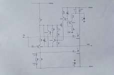
For inspiration, I'm attaching a quick, night-time sketch. A well-known way to virtually establish a kind of class A.
A nice playground that not only copes with 8 Ohm loads without restrictions, but of course also makes a super cool headphone amplifier.
The circuit does not use a balanced +/- operating voltage. When used with headphones, the huge output coupling capacitor is reduced to three 100µF types connected in parallel.
greetings,
HBt.
maybe you will find the solution in the final circuit of the 3/4 + 3/4 amplifier design or in a quick test setup, measurement supported trial and error procedure.
Or more deduction 😉.
Absolutely.Yes, this shows a problem in a somewhat different implementation of an idle-current control loop but I suspect that any version that uses the same front end to control both functions could exhibit similar kinds of problems. Worth looking at, in terms of simulation results anyway.
For inspiration, I'm attaching a quick, night-time sketch. A well-known way to virtually establish a kind of class A.
A nice playground that not only copes with 8 Ohm loads without restrictions, but of course also makes a super cool headphone amplifier.
The circuit does not use a balanced +/- operating voltage. When used with headphones, the huge output coupling capacitor is reduced to three 100µF types connected in parallel.
greetings,
HBt.
Unfortunately, this is a well-known problem! Have you already tried ramping up the supply voltages slowly?This simulation shows the result of one cycle, used to kick-start a problem I found in the idle-current feedback loop. The plot shows the current flowing through one of the 1-ohm sense resistors. The current is matched by an equal but opposite flow in the other sense resistor, so the output voltage shows nothing....at least, over this time frame. It surely would in a real-world implementation.
I wouldn't do that, but please don't ask me why - that's going a bit too far for me.Examination of the schematic shows that I split the offset-setting resistors into two parts so I could insert C3 in there. The idea was to short out the opposing phases of the idle-control loop oscillations (...)
In principle, it is precisely this investigative approach that is to be welcomed, Sine-burst'sBut it gets worse. If I simulate the result of a burst that lasts long enough for the loop to enter its class AB mode and then turns off:
Attachments
Ramping the supplies did not improve the results of my simulations. I'm not convinced my results are accurate, still playing around with some sanity checks.
Thanks for your comments.
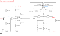
I separated the signal and idle-current paths in another version. Shown below, it works much better in terms of idle-current stability.

This explores just one way to control the idle current using a closed-loop technique. It's something I have been interested in for quite awhile, so recent discussions regarding the MF-A1 and variations have been quite interesting to me.
Thanks for listening.
-Mark
Thanks for your comments.
I separated the signal and idle-current paths in another version. Shown below, it works much better in terms of idle-current stability.
This explores just one way to control the idle current using a closed-loop technique. It's something I have been interested in for quite awhile, so recent discussions regarding the MF-A1 and variations have been quite interesting to me.
Thanks for listening.
-Mark