Guys,
I want to build Aleph J as a speaker/headphone amp. How big is offset in your builds? Is it stable? How does it change overtime with warmup? A friend of mine has built it and shared that offset is not rock solid and can be a bit much for headphones.
In that case I guess I need a DC servo, right? Has anybody tried that? Or am I the first crazy to use that amount of amp for headphones 😉
Aleph J DC offset will change as the MOSFETs heat up. However, it is nothing to worry about. I suppose you should be able to get the DC offset (warmed-up) to be within + and - 10mV. Others have reported even smaller variations.
I suppose you could use the headphones, but only if the DC offset stated above is not a problem, and only once the amp is warmed up.
You could try to place a capacitor in series with amp output to block the DC offset completely; however, you will still have to be careful not to plug the headphones in while the amp is cold because the DC offset will charge the capacitor and then your headphones coil will discharge it when you plug them in - something you do not want to do. Note that ACA has a 1K resistor connected in parallel to the speaker binding post to help discharge this stored potential.
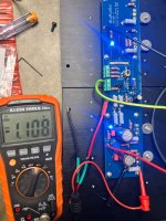
Did you forget the keratherm sheets...???I am trying to set the bias using R27 pot without success. the V across the R19 is very close to 1V with no change. Any idea?
I see that you bypassed C1. Has that amp ever worked correctly?
It seems that you bent the trimpot legs to be able to solder them... I am not 100 sure, though. However, if you did bend the legs, make sure they haven't snapped.
Is DC offset okay? Can you change the DC offset?
That's too high a bias current. Make sure the MOSFETs are electrically isolated from the heatsinks, and check the soldering.
You will have to provide a bit more details. I have attached two photos; one shows the correct voltages, and the second (generic fault-finding instructions for the Aleph J amp) shows what voltages you should measure to properly fault-find the problem. Give us more details, and we'll be able to help you further.
Last edited:
There are pad under the MOSFETs. This is the second channel. The first one is perfect in all respects
inputs shorted, no load at output?
both rails confirmed at channel pcb?
try posting better/clearer pictures, some of Boyz could catch something, even if I'm personally simply unable to grasp this iteration, it's too much confusing for my Piglet brain
both rails confirmed at channel pcb?
try posting better/clearer pictures, some of Boyz could catch something, even if I'm personally simply unable to grasp this iteration, it's too much confusing for my Piglet brain
No issue, The other channel works beautifully.I see that you bypassed C1. Has that amp ever worked correctly?
No issue, The other channel works beautifully.
You have a few options to find the problem. Carefully compare the good-working module with the faulty one.
The interesting thing is the very high current draw through the MOSFETs despite the fact that the bottom half of the MOSFETs (Q7 and Q8) should not be conducting judging by the 34mV measurement taken accross the trimpot R7.
The top half is "fully open" (5.2V) and conducting, but based on that 34mV measurement, there still shouldn't be any current running through the top and bottom MOSFETs. However, according to the values you provided, there's double the normal amount of current running through the MOSFETs at the moment... that would be quite hot indeed... approaching 50W total dissipation per each MOSFET...
I mentioned in my first reply to you to check the trim pots. Make sure they are the correct value, soldered correctly, and their legs have not been snapped off. Remove both boards and do a slow, step-by-step double-check of everything. Make sure that the transistors are properly soldered as well.
Good luck.
since i'm using powercon ac in instead of back panel kit do i still need both fuses ,and what size fuses for 120vac?

Good morning Patrick!
Got it. I was thinking he might be using some kind of power conditioner or gang box that was fused.
Got it. I was thinking he might be using some kind of power conditioner or gang box that was fused.
- Home
- Amplifiers
- Pass Labs
- Aleph J illustrated build guide