And he's been in business as essentially a one man operation for more than 20 years so things seem to be working well.
I'm still trying to find someone on the board who can point me in the direction of a circuit like used in his Linear B amp. Its a hybrid solid state driver into a EL84.
To quote from the review linked.
“The input and driver stage’s remaining 3rd order added harmonics are better than minus 140 db below the signal. The output stages are two composite tubes each made from 4x EL84s in parallel per side to form two large power tubes running in class A with local feedback (ultra linear) used to reduce any remaining 3rd order harmonics. This breakthrough results in harmonic distortion well below signal level. Additionally, there are no other higher order harmonics produced by the unusual output stages. We also took this approach to avoid the very poor intermodulation distortion figures inherent in all conventional tube amp designs.
“The circuits are also DC coupled throughout avoiding any added coloration of signal caused by AC coupling capacitors in the signal path. Signal bandwidth at 1 Watt is 10 Hz – 190 kHz. Running them at full power, the signal bandwidth is still 10 Hz to over 50 kHz, but running at full power would be way too loud to remain in the listening room with them. The composite tube output stages also have an inherently low output impedance and will drive 2.5 Ohm loads when switched to zero global feedback. We also found that adding global feedback causes dynamic compression of the signal.
See review below of the matching preamp and his long running hybrid tube amp.
Part Time Audiophile. Mastervibe and Linear B
Last edited:
I sure hope so. I was commenting specifically on the quality of the build. I haven't evaluated their circuits as I have no interest in buying one of their products.Noise (EIN), MC 65 mV A-weighted, 105mV flat,
That a typo you figure?
Appeal to authority is not an argument in my view. I have great respect for both, but what they said decades ago may not apply today. Heck, what they said yesterday may not apply today. Things do change. They also have the right to change their opinion. And I have the right to disagree with them and express that disagreement.There are good reasons for using multiple regulators -- separate ones for each channel being chief amongst these. Ask Jan... and Walt. And the builders who've been happy they did.
My skepticism of multiple regulators in series is rooted in engineering. I doubt you will be able to measure any difference in the output of a phono stage with/without the multiple stages of regulators using modern parts. I'm more than happy to be wrong on this. If you have a measurement that shows I'm wrong then I'm happy to discuss further.
Sure. Many commercial manufacturers argue that their DACs are better because they have femto-second jitter clocks in them. Never mind that the first thing that fs clock 'sees' when it enters the DAC chip is a clock jitter cleaner. This means that the DAC runs on its own internal VCO and as long as the input clock isn't horrifically noisy the DAC will provide good performance. The 50 ps jitter clock that comes from the SPDIF receiver is plenty good, but manufacturers still use fs clocks even though they make no difference in the DAC output. Why? Because it sells. It's a way of saying, "our product is special. THEIR product is NOT special. You should buy OUR product".Many commercial manufacturers argue for their products on the basis of their design decisions. A multitude of regulators is not a rare argument though most haven't designed their own regulator. Sales pitch? Marketing? Technical exposition? All three?
Many design decisions are made because the consumer wanted them and not because they make any difference in the audio performance of the product. Take OLED displays. Or volume controls with a certain feel.
I can also think of several psychological effects that would explain why someone, say a reviewer, might hear an improvement from such "special" circuitry even though the special secret sauce made no difference on the audio output.
Tom

Why does it have to be all or nothing?So are we near the end of the era of regulation of power supply rails in audio?
There are cases where supply regulators are appropriate and there are cases where they aren't. What manufacturer A considers appropriate might be different from what manufacturer B considers appropriate. I think there's room for nuance here.
Tom
That's not respectful of what I said.Why does it have to be all or nothing?
Unlike these unilateral appraisals of the Mastergroove.I think there's room for nuance here.
All this reminds me of a favourite passage from Dick Marsh's Pooge 3 article in TAA from 1985:
" Symmetry of Thought and Design
As with most subjects, there is a symmetry to audio design. The tendency is to modify or refine what you already have, but this limits the possibility of a better solution. If you think of an idea symmetrically -- i.e. in its mirror image or opposite state -- the possibilities for advancement are much greater because you are able to consider everything between the extremes.
For example, if you learn that certain types of capacitors have non-ideal characteristics that can be audible, the tendency is to find a more ideal type and substitute it. The symmetrical approach would be to consider what would happen if you had no capacitor at all. This would force you to think of how you could make such a design work. Perhaps you could use a direct-coupled design (the best solution) or add direct-coupled/ servo circuitry to reduce drift and offset. With this approach, you can end up with a better, less expensive product than if you had refined the original idea.
Another example is power supplies. Some nice things, such as improved channel separation and better imaging, happen to the sound with added supply capacitance. Normally, our solution would be to build bigger supply capacitor banks. This gets ridiculously out of physical and monetary sight, so you might resort to electronic capacitance multipliers. From there, it is a short step to the ultraregulated supply, and the evolution continues.
It became clear to me that the power supply must approach the same level of sophistication as the amplifier, with diminishing returns. The symmetrical approach was to design an amplifier that was immune to the effects of the non-ideal supply interface interactions.
Power Supply / Amplifier Interactions
I have since found that the amplifying stage and its power source interact in certain ways. I discussed some of those interactions in a brief overview of power supplies (TAA 3/83, p. 16). Still it is not generally recognized that you can reduce stage-to-stage and channel-to-channel power supply effects in two basic ways.
First, you can make the power supply very "stiff" and give it a very low Z. Amplifier load demands then cause only minor perturbations. Conversely, you can make a circuit that is immune to the effects of power supply loading / modulation and nonlinearities. In that case, a regulated supply is not (or at least is less) needed. I concentrated on how to improve the amplifying circuitry to give it greater immunity to power supply problems. "
Is that approach nuanced enough?
You're certainly right that tunnel vision can be a thing in the design process. I often find it helpful to let a design (or PCB layout) rest and come back to it after a while.
A very 'stiff' power supply can be made with any of the modern regulators. Adding regulators in series won't help you there.
A modern regulator like the TPS7A47 from TI has 82 dB of ripple rejection at 100 Hz. The OPA828 has 118 dB PSRR at 100 Hz. That's a total of 200 dB of attenuation. This means that if you have 10 V ripple on the power supply you'll get 1 nV of that ripple on the output of the opamp.
It's a bit worse on the negative supply ,where the OPA828 'only' has 110 dB PSRR at 100 Hz. The negative regulator (TPS7A33) has a bit worse line rejection as well with 'only' 72 dB of rejection, so you 'only' get 182 dB of attenuation on the negative supply, so now 10 V ripple on the power supply will result in 7.9 nV on the output. You really think that adding more regulators will have any impact? Also, any interaction through the power supply is attenuated by a minimum of 110 dB as that's the PSRR of just one opamp plus the attenuation caused by the regulator output impedance.
I don't doubt what Dick March wrote in the early/mid 1980s was true to him at that time. But the world hasn't been at a complete standstill since then. I also don't doubt that one can design a circuit where all your points would be true. I would argue that such a circuit isn't getting state of the art performance, but maybe your design goals are different from mine. That's fine.
Tom
I quoted Dick Marsh for the philosophical approach he espoused. Of course he was applying it to the problems that presented themselves to him at the time. Pursue his approach and the issues change, diminish or disappear. And all of a sudden it's 2024.
I wasn't arguing for pre-regulators per se... just pointing out that others had used them -- like Evans -- and reported benefits. I have no horse in this race.
I may use them but chiefly to be able to present the primary circuit regulators with an optimal voltage that won't generate a lot of heat in a small signal case. The pre-regulators would be in a remote PSU.
However, you've pointedly disregarded the question of separate regulators for each channel. Are these negligible too? Even today?
Hope this helps.
I get lots of questions on this. I generally make the point that if you use a superreg for an opamp circuit, a prereg is unnecessary. It won't hurt, but I would spend my money elsewhere, where it actually improves the audio reproduction.Appeal to authority is not an argument in my view. I have great respect for both, but what they said decades ago may not apply today. Heck, what they said yesterday may not apply today. Things do change. They also have the right to change their opinion. And I have the right to disagree with them and express that disagreement.
Jan
Sometimes specmanship leads its own life. If 80dB channel separation is good, 100dB is clearly better.
But when I did measurements on LP record reproduction many years ago, the very best combination of record and cartridge I measured was 30dB channel separation between L and R over the audio band, with an occasional few dB better at specific narrow frequency bands.
IIRC the Boulder quotes 100dB channel separation, and I wonder how much effort has gone in this impressive but totally useless performance.
Jan
I watched that video on another forum (UK Vintage Wireless). I have however read this entire thread, and unless I am wrong no one has mentioned the hundreds of bead tantalum capacitors, one of which had failed short circuit.
Anyone who has fixed gear with bead tantalums, particularly in power supply duty, know that they will and do short circuit, often burning clear through the board, or exploding. Tektronix oscilloscopes (7000 series and plugins) are (in)famous for this. And also Datron system DVM's.
What's the bet that this bizarre phono stage will be back for repair when the next tantalum gives up the ghost?
Craig
Hi Ken,Okay, I think I see how it works. Those four resistors determine the AC gain of the closed-loop. Which is equal to the R6,R11 and R10,R5 divider ratios. So, 750/22R = x34 = +30.6dB closed-loop gain.
I think your question is quite valid.
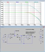
Look at the two attachments, the first being the circuit as is, but for simplicity without servo, the second version is without R10/R5.
Both deliver the same 30.6dB output gain, but the difference is that in the original version, the line output after being divided by 34 by R6/R11, is then amplified again by a factor 34 by IC-2b and finally attenuated again by 34, resulting in the same amplitude as Vin.
When giving IC-2B a gain of 0dB, its amplification and attenuation is removed, but still with a Line Output that has a 34x amplified input signal.
By purpose I didn't use a very fast 5Mhz op-amp to show that the original version's only benefit is that you slightly increase the BW at the cost of some peaking at HF.
In terms of phase turning, version 2 has a group delay of 886nsec at LF and 876nsec at 20kHz, so this fits the most critical bill.
But on the other hand, IC-2b with a gain of 30.6dB will have a much higher THD as with 0dB gain, and while it's signal being fed back to IC-2a this will result in a higher overall THD.
Unfortunately, THD for opamps in LTSpice are not well implemented in their models, so I can't demonstrate the effect.
Hans
Attachments

On the other hand... remind me how effects like the degradation of channel separation work.Sometimes specmanship leads its own life. If 80dB channel separation is good, 100dB is clearly better.
But when I did measurements on LP record reproduction many years ago, the very best combination of record and cartridge I measured was 30dB channel separation between L and R over the audio band, with an occasional few dB better at specific narrow frequency bands.
IIRC the Boulder quotes 100dB channel separation, and I wonder how much effort has gone in this impressive but totally useless performance.
Jan
If you have serial stages each with poor channel separation is the separation "in" improved or worsened or stay the same by the time the signal exits the chain?
Is a 30dB input preserved if followed by a second 30dB stage? An 80 dB stage? A 100dB stage?
Perhaps the poorer the channel separation you start with means that it is more important to not make it worse with subsequent components?
Unless you're aiming at monophonic sound.
Just wondering...
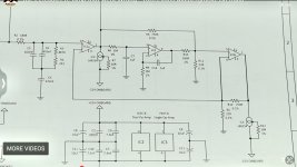
Thanks, Hans, for that analysis. No doubt, my following conclusion regarding that particular design feature will get the thread further attacking the unit, but here goes. The purpose for IC2b, is the overlaying a certain distortion character/profile on to the stage. That’s just a logical presumption, of course, but your circuit analysis helps to further solidify that thinking. As you indicate, its presence degrades (contours?) the distortion.
While I don’t automatically have a problem with a philosophy of distortion character contouring, I’m also not looking to get into the usual objective vs. subjective performance fight with anyone. I do, however, suspect that certain dynamic distortion behaviors are the reason why some equipment, typically tube gear, often is said to sound more realistic. Particularly, against components featuring subjectively undetectable distortion. A notion which, while not yet proven, does make some logical sense, but I don’t know. For what they may be worth, I read several product reviews of this model. All of which focused on the subjective realism of reproduction as its most outstanding feature.
For the benefit of others, here is a more easily read image of that line-output amplifier section of the schematic:
Attachments
Last edited:
I think the idea of this circuit is error cancelling to the degree the opamps match as both amp run the same gain and see the same load and pin potentials.... I might to a sim with real distortion in the input stage of the opamps later tonight to check what is really happening....But on the other hand, IC-2b with a gain of 30.6dB will have a much higher THD as with 0dB gain, and while it's signal being fed back to IC-2a this will result in a higher overall THD.
Unfortunately, THD for opamps in LTSpice are not well implemented in their models, so I can't demonstrate the effect.
Pre-regulators are rarely needed with SilentSwitcher. The DC-DC converter used in SilentSwitcher provides line and load regulation and acts as a pre-regulator for the output regulators. But as there is no galvanic isolation ground noise from power source can leak through so I would avoid noisy SMPS power sources with SilentSwitchers.Jan, before the SilentSwitcher... how many super regs would you use?
@bohrok2610
That wasn't what I meant.
I was asking "pre Silent Switcher"... before there was a Silent Switcher... what would his approach be.
That wasn't what I meant.
I was asking "pre Silent Switcher"... before there was a Silent Switcher... what would his approach be.
Errors created by the first amp can never be cancelled by a second that's behind the first one.I think the idea of this circuit is error cancelling to the degree the opamps match as both amp run the same gain and see the same load and pin potentials.... I might to a sim with real distortion in the input stage of the opamps later tonight to check what is really happening....
That would only be possible when the second amp received input + output signal from the first amp in a nested feedback.
Hans
You may stop wondering.On the other hand... remind me how effects like the degradation of channel separation work.
If you have serial stages each with poor channel separation is the separation "in" improved or worsened or stay the same by the time the signal exits the chain?
Is a 30dB input preserved if followed by a second 30dB stage? An 80 dB stage? A 100dB stage?
Perhaps the poorer the channel separation you start with means that it is more important to not make it worse with subsequent components?
Unless you're aiming at monophonic sound.
Just wondering...
I can (almost) do that from the top of my head. dB's are easy when you grok it.
If I have a system with 30dB separation followed by a system with 'only' 100dB separation, the original 30 dB separation deteriorates to 29.99777dB separation (rounded up to the next microdB).
Jan
the thing is, if the original separation is relatively low, you really don't want it to deteriorate at all.
sure, the deterioration is small... but it is deterioration and the lower the initial separation, the greater the percent deterioration.
Thanks for confirming how this works.
and no I wouldn't be buying based on these specs.
sure, the deterioration is small... but it is deterioration and the lower the initial separation, the greater the percent deterioration.
Thanks for confirming how this works.
and no I wouldn't be buying based on these specs.
That would be very hard to predict.I watched that video on another forum (UK Vintage Wireless). I have however read this entire thread, and unless I am wrong no one has mentioned the hundreds of bead tantalum capacitors, one of which had failed short circuit.
Anyone who has fixed gear with bead tantalums, particularly in power supply duty, know that they will and do short circuit, often burning clear through the board, or exploding. Tektronix oscilloscopes (7000 series and plugins) are (in)famous for this. And also Datron system DVM's.
What's the bet that this bizarre phono stage will be back for repair when the next tantalum gives up the ghost?
Craig
I worked for more than 19 years in the industrial electronics manufacturing industry and yes, bead tantalum capacitors would be among those with a somewhat higher failure rate, but nothing alarming. Their bad reputation probably has something to do with their spectacular failure mode when powered with enough current, but usually they would fail in the same way as in Mark's video, without any visual clues.
That bad reputation led to some products being (re)designed with primarily MLCCs, but these certainly also have a higher than average failure rate as they are prone to cracking.
During the introduction of the leadfree soldering process, we noticed a much higher failure rate of SMD tantalum caps, some quite destuctive (again, depending on the current limit of the power supply). After a while it was found out that there were derating rules in the datasheets that practically meant that the rated voltage should be twice that of the applied voltage. In other words, at a voltage of 16 V, a 25 V tantalum would not suffice (anymore?). After BOMs were changed, things went back to normal, but the reputation stayed.
- Status
- Not open for further replies.
- Home
- Member Areas
- The Lounge
- The £25,000 preamp that went wrong - Tom Evans Mastergroove