measurement is not music.
Without more information - description and pictures of your build as Craigl59 suggested, and measurements as MEPER suggested - it would be impossible to diagnose your issue.
Perhaps you need a psychic.

Avoid sarcasm please. Education is valued.Without more information - description and pictures of your build as Craigl59 suggested, and measurements as MEPER suggested - it would be impossible to diagnose your issue.
Perhaps you need a psychic.
It's called a dynomometer.How to measure a car engine without connecting it to the car.
Please send a picture of your board/s. Kind of hard to evaluate anything without anything. There is nothing wrong with the design. It is working perfectly for hundreds of people. I love mine.
the misured frequency response of this preamp is very good 😋Measurements are objective.
A lot of time can be wasted listening to something that are not fully tested before it is used in the system.
If no sinus generator is available "test CD's" can be streamed to be used instead. They have fixed frequencies, sweeps, phase test etc.
Attachments

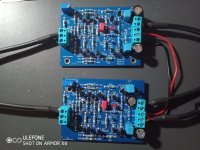
I am reading 2.2 volts at the ouptut and when I adjust the pots there is no change. LEDs are both on and same behviour with both boards.
After hooking it up to my power amp (Akitika GT-104) there is sound but then when the volume is slightly increased from minimum, it goes silent and there are some slight clicking noises. hmmm... Wondering if I mixed up a component, I did also solder the boards in tandem explaining the same behaviour.
After hooking it up to my power amp (Akitika GT-104) there is sound but then when the volume is slightly increased from minimum, it goes silent and there are some slight clicking noises. hmmm... Wondering if I mixed up a component, I did also solder the boards in tandem explaining the same behaviour.
@Woofer&Sons When I have been unable to adjust the DC Offset have looked first to the SMDs. Check the continuity of these first; only the left board is shown in the BoM schematic. The right side can be inferred from the left (it is mostly parallel reversed) or you can download the complete schematic from the beginning of this thread. The fact that both boards are showing the same 2.2 volts suggest the same error (as you note). Check the KSA1992 and KSC8145 values carefully against the on-board labels. The good folks on this thread will get you running but let us know each step you pursue.
@Woofer&Sons your upper board looks like it's missing a power supply ground connection. And it may be the angle of the pic but the input jumper on the lower board looks to connect In+ to GND.
I have a 24VDC power supply (2 wires) hooked to +V and -V terminals with correct polarity and jumperd over correctly to the 2nd board. I was confused with the ground connection, does this need to tie to the -V supply or to a metal chassis ground. Right now it is not tied to anything.
This preamp requires a dual rail supply. You should have 3 wires coming for your power supply. +24 GND -24. I think +-24V might actually be a little too high. IIRC +-18 was recommended. What are you currently using for your power supply?
Last edited:
I found a cheap 24 VDC supply I had laying around for another project (Arylic plate amp for boombox build) and was contemplating whether it was appropriate. I had the urge to try it though...
Any suggestions for a suitable supply would be welcome!
Any suggestions for a suitable supply would be welcome!
I highly recommend RKThatcher's FlexReg PSU -- available directly from him on this site. It allows you to adjust the vdc from 15 to 24 and works splendidly. I use two of them for the WB2018, one for each channel. You might find this overkill but it depends upon your system and expectations. Contact Randy who is a fine professional and a particularly important contact.
- Home
- Amplifiers
- Pass Labs
- Wayne's BA 2018 linestage