45, the initial aim of this thread was to present results on contemporary OPTs - so there is no other option than to accept the transformers for what they were back in late 1940's. If measurements of a modern OPT, with a modern lamination option and winding configuration becomes available then that would be a great way to round out the 'view'.
My frequency response measurements actually included distortion data, as per post #41 results, so I will update the on-line doc asap. I did quickly look at the WWFB data and its equivalent distortion at 20Hz had the 3rd HD at about 0.11%, and 5th is about 0.035%, so quite noticeably lower.
My frequency response measurements actually included distortion data, as per post #41 results, so I will update the on-line doc asap. I did quickly look at the WWFB data and its equivalent distortion at 20Hz had the 3rd HD at about 0.11%, and 5th is about 0.035%, so quite noticeably lower.
45, the initial aim of this thread was to present results on contemporary OPTs - so there is no other option than to accept the transformers for what they were back in late 1940's. If measurements of a modern OPT, with a modern lamination option and winding configuration becomes available then that would be a great way to round out the 'view'.
My frequency response measurements actually included distortion data, as per post #41 results, so I will update the on-line doc asap. I did quickly look at the WWFB data and its equivalent distortion at 20Hz had the 3rd HD at about 0.11%, and 5th is about 0.035%, so quite noticeably lower.
In my experience, the higher distortion is due to the air gap which is uneven. So where the airgap is smaller you have less reluctance and a lot more flux is going through there and in reality those 10 Vrms account for higher local induction B than one is assuming.
There are 2 possibilities: 1) laminations or C-cores are not best quality 2) the method for putting the pieces together could be improved.
Of course can be both....
I know you are just measuring what you can find but even the same nominal transformer has tolerances coming from both manufacturing and different lots of cores. If one does what he can it's fine, if one wants to reach the best he can than this becomes a requirement. That's all.
Been noodling this over -- you can't measure the magnetizing inductance and secondary inductance with the same level of stimulus. Better idea, calculate the approximate turns ratio using a signal level close to that the DUT will experience for 1W. Measure the inductance of the primary (L_magnetizing + L_leak) with the secondary open with this signal level.
Next, iteratively measure the inductance of the secondary varying the secondary stimulation, arriving at the inductance level which would have been predicted by the turns ratio.
With that number in mind, measure the voltage on the secondary.
All of the lossy components should fall out.
Next, iteratively measure the inductance of the secondary varying the secondary stimulation, arriving at the inductance level which would have been predicted by the turns ratio.
With that number in mind, measure the voltage on the secondary.
All of the lossy components should fall out.
With that number in mind, measure the voltage on the secondary.
I meant primary winding
45, whether a particular test of a transformer is a challenge to you is not per se the issue - and similarly if you aren't embracing the Williamson philosophy then again that is not per se an issue wrt this thread.
Nope, may be it's you that are too much into your ideas and do not see things from other's perspectives.
It's just not worth!
I am not embracing the Williamson philosophy because I have been there and those amounts of GND feedback simply do not work except on paper. I will take the Olson 6F6 parallel PP every time.
However the original circuit could work fine with few adjustments. I do not think I am subjective on this aspect. Leaving DHTs out, several forms of local feedback work a lot better in every way if wanna get low distortion numbers at any rate. This also means that other transformers would be suitable for the "modified Williamson" and worth measuring which is perfectly in topic...
By the way I entered this thread because you were writing a wrong OPINON of the Sowter transformer...for the same reason you are telling everyone is off topic as soon as you don't like it. I really do not understand why you are posting here. Just open a personal blog where talk to yourself and cancel everything you don't like.
I am out no worries....
Last edited:
 Some discussion has been split to here -
 Hi trobbins, Is it possible for you to share the schematics for the balanced line driver? I need to test some small PP headphone OPTs with REW using your method and I don't have any idea about the balanced driver.
Any help will be appreciated.
Sajad
Any help will be appreciated.
Sajad
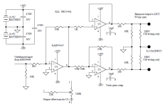
Hi Sajad, attached is what I used for the balanced line driver in Fig.3 of the on-line doc.
I also started to look at using higher power levels. One method is to use a stereo ss PA amp as the balanced driver (some amps have integrated bridge mode circuitry with a balanced input), the OPT is placed across the outputs of the two channels to effectively double the available signal voltage swing. Given a typical 300W amp with a common +/-80Vdc rail for both amp channels, the effective PP drive signal is up to about 2x 80V = 160Vpk. That is 113Vrms, which for a 10kPP OPT could allow testing to 1.3W. But I didn't formally continue down that path at the time.
I also started to look at using higher power levels. One method is to use a stereo ss PA amp as the balanced driver (some amps have integrated bridge mode circuitry with a balanced input), the OPT is placed across the outputs of the two channels to effectively double the available signal voltage swing. Given a typical 300W amp with a common +/-80Vdc rail for both amp channels, the effective PP drive signal is up to about 2x 80V = 160Vpk. That is 113Vrms, which for a 10kPP OPT could allow testing to 1.3W. But I didn't formally continue down that path at the time.
Attachments

Thank you so much trobbins. In regard to using a class AB SS amplifier, the NE5534 driver should be placed in between the soundcard and the amp, am I correct?Hi Sajad, attached is what I used for the balanced line driver in Fig.3 of the on-line doc.
I also started to look at using higher power levels. One method is to use a stereo ss PA amp as the balanced driver (some amps have integrated bridge mode circuitry with a balanced input), the OPT is placed across the outputs of the two channels to effectively double the available signal voltage swing. Given a typical 300W amp with a common +/-80Vdc rail for both amp channels, the effective PP drive signal is up to about 2x 80V = 160Vpk. That is 113Vrms, which for a 10kPP OPT could allow testing to 1.3W. But I didn't formally continue down that path at the time.
It would depend on the amp, and its inputs and their sensitivity, and whether it can operate in bridged mode.
Thanks again, so all is needed is a bridgeable two channel amp and two anode taps of the PP OPT should be connected to speaker terminals of the bridged amp and the center tap should go to common ground? Am I correct?It would depend on the amp, and its inputs and their sensitivity, and whether it can operate in bridged mode.
Depends if you want to model the response with the effective anode resistance of a push-pull amp.
That's exactly what I am trying to accomplish.Depends if you want to model the response with the effective anode resistance of a push-pull amp.
Thanks again
Yes I've read your article on Williamson transformers and I'm too using REW for measuring SE OPTs for a while now.added 1.25k resistors between amp and OPT - is that your intent too?
I always used reverse method with SE OPTs and in this method I normally use a resistor equal to nominal speaker load in series with SS amp output in series with transformer secondary and on the primary side I load it with a resistor equal to nominal primary impedance and take the signal from a voltage divider into the Scarlet 2i2.
This method only works for SE transformers since one side goes to B+, but in regard to PP OPTs the center tap goes to B+ and grounding one of the plate taps won't show the correct F response, so I probably use your method for this.
Thanks
Sorry, can I have one more question; I found this class D mono amplifier module in my parts box which seems to be in BTL configuration: https://www.icstation.com/mobile/m5...el-audio-amplifying-board-module-p-13123.htmlJust checking, as you indicated the amp would connect directly to OPT.
Is it possible to use this for loading the PP OPT?
You are likely to have grounding problems, as the output of a class D is floating with respect to input.
Oh you're right, so it seems I can't use the ground as the center tap between two output speaker terminals. I guess I need to find a way to bridge my 300W class AB stereo amp...You are likely to have grounding problems, as the output of a class D is floating with respect to input.
Thanks for all your help.
- Home
- Amplifiers
- Tubes / Valves
- Measurements on output transformers for the Williamson amp