I indicated these two n.f parts in the picture. BOM and schematic do not list any info about these values.


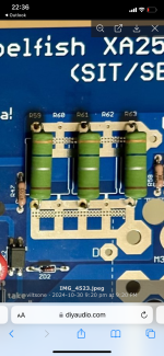
Depending on whether the third ring is gold or silver (difficult to see) either 4.6 ohms or 0.46 ohms.
It's probably silver, so 0.46 ohms, and it gives 0.15 ohms instead of 0.11 ohms.
It's probably silver, so 0.46 ohms, and it gives 0.15 ohms instead of 0.11 ohms.
It is 0.36 ohms Jantzen audio Supreme 5W resistors.Viltsone, what value of resistors are you using. Combined value should be around 0R11, meaning 3 // 0R33 resistors.
Yes.Is the first ring orange? On the picture it seems to be yellow.
I really need some help. Does some one have populated the same pcb 2023 version (V. march 2024). I populated new board and same thing that it blows negative rail fuse right a way. I checked everything and it seems to be all right. Are the part like TH1 (TS820-600T), Q9(TTC004b), Q1 (TTC004b), Q2 (TTA004b), M2 (DN2540N5), M3 (IRFP140), M4 (IRFP9140) put the same way like they should be? Other transistors Onsemi BC63916-D74Z, BC640TA, BS170, BC546CTA, Sharp PC817X3NIP1B, Texas Instruments LM385BLPRE3-1-2, Vishay BZX55B8V2-TAP and BZX55B12-TAP.
Any ideas and what next?


Any ideas and what next?
Do you have insulator where the two transistors are mounted to the one small heatsink on the board?
These are full plastic and do not need to have isolator.Do you have insulator where the two transistors are mounted to the one small heatsink on the board?
Viltsone, have you tested without output FET's?
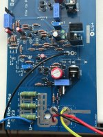
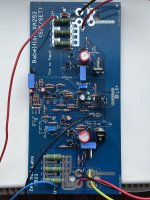
here it is - testing only FE
steps are - removing pucks from game , so no nasty surprises
establishing NFB loo ( broken without pucks in place) so FE is having all what's necessary to behave
here it is - testing only FE
steps are - removing pucks from game , so no nasty surprises
establishing NFB loo ( broken without pucks in place) so FE is having all what's necessary to behave
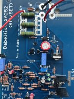
Looking at Zen Mod's schematic I see components that are specified to be omitted for the all MOS version. Looking at the pictures I can see R48 installed although it is one off the omitted components. I have not checked for other components that should not be installed as component designations on the picture of the pcb were not easy to see.
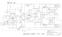
you populated all parts, while there are 3 separate and distinct schematics for each iteration:
which of these you intend to build?
actual schmtcs clearly linked in Post #1, leading to post #1462 https://www.diyaudio.com/community/...2-sit-babelfish-xa252-set.373443/post-7560120
- full MOS
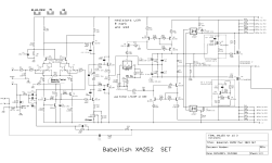
- Schade-d MOS (SET)
- SIT in place of N-channel MOS (SIT)
which of these you intend to build?
actual schmtcs clearly linked in Post #1, leading to post #1462 https://www.diyaudio.com/community/...2-sit-babelfish-xa252-set.373443/post-7560120
I built Schade-d MOS (SET) version using MOSFETS IRFP140 and IRFP9140 for the output. Have I done it wrong? 🙄 My schematic is a little bit newer version from may 2024. One zener diode is replaced with a mosfet.
Should I upload the schematic that I used? @Zen Mod These resistor names are different for example R43 47ohm from linked schematic is the same as I have R48.
Should I upload the schematic that I used? @Zen Mod These resistor names are different for example R43 47ohm from linked schematic is the same as I have R48.
Attachments
Last edited:
I think there are some issues with the parts. For example, you use for R18 100K if Isee it correctly - but it should be 100 ohms only; GBR should be 0R, yours is 15 ohms, R14 100ohms, it should be 120 ohms, R10 120 ohms, should be 220 ohms...
I would recommend to crosscheck the parts very carefully with the schematics in this post (SET).
Could you upload your schematisc?
I would recommend to crosscheck the parts very carefully with the schematics in this post (SET).
Could you upload your schematisc?
Last edited:
Have I done it wrong?
minor change is small TO92 mosfet as cascode to LT3092, in place of upper series zener
anyhow, you have proper set of schmtcs, and major error you did is - while having all level shifting parts installed (to enable SET mode) , you also have unnecessary installed R50, which is shorting same stage
circuit is simply unable to bias outputs as constructed
cumulative schm (that one not functional, just showing all parts on pcb) and SET iteration schematic attached; also parts placement
Attachments

Hi Mighty, what about this post? https://www.diyaudio.com/community/...2-sit-babelfish-xa252-set.373443/post-7560120 the parts have different numbers, that's why I thought @viltsone uses wrong values 🤔 R18 there is in your above schm R16, f.e.
it's normal (at least with me) to make some revisions with time, especially with circuits so complex as this one
so, some understanding of circuit is necessary, at least in measure to spot possible differences in schematic(s) and then to ask here
so, some understanding of circuit is necessary, at least in measure to spot possible differences in schematic(s) and then to ask here
Last edited:
Okay, does it mean that there are different pcb's for the different schematic versions (I mean early, late, not SIT, SET,...)? So my pcb is based on a prevoius schm?
Good to know, thanks. I think I also have to make a check and maybe repopulate my boards 🤔
Good to know, thanks. I think I also have to make a check and maybe repopulate my boards 🤔
- Home
- Amplifiers
- Pass Labs
- Babelfish XA252 / Babelfish XA252 SIT / Babelfish XA252 SET