Mayday you can also use a single transformer, a single rectifier bridge... The one in the picture fits perfectly.
Yeah I figured I could, but to get the most of this design I would like to make it dual mono in every way except the stepped attentuator I plan on using(so a stereo pot instead of two mono pots).Mayday you can also use a single transformer, a single rectifier bridge... The one in the picture fits perfectly.
I think I can use two bridge rectifiers/transformer if I make a "Y-connection on the centre tap? Hard to explain in text, but like this:
-----12vac
-------0
---<
-------0
-----12vac
Above showing one transformer.
Edit: my attempt at showing the Y-connection is not looking good once posted 🤣
Anyway, a Y-connection giving two "0" from the centre tap.
I have enough of those centre tapped 12Vac transformers that I might as well go dual mono as have them lay in a box.


Another question.
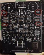
I've got both BC3x7-25 & BC3x7-40.
If I get closer matches with a mix of those than within one of those (-25 & -40), is it a good idea to mix...or should I stick to the best matches within the -25 range of the BC3x7's?
I've got both BC3x7-25 & BC3x7-40.
If I get closer matches with a mix of those than within one of those (-25 & -40), is it a good idea to mix...or should I stick to the best matches within the -25 range of the BC3x7's?
From skimming through the data sheet, there should not be any issues mixing BC3*7-25 & BC3*7-40. There's some overlap in Hfe ranges between them, so chances are I'll get more closely matched transistors matching from twice as many transistors 🙂
You can use 12-0-12 transformers but with a single bridge rectifier instead, i used a 12-0-12 transformer for a while without issues. As for VA rating my 12 VA transformer got pretty warm but when i used the BOM dual mono boards. After swapping to a de-noiser psu it gets lukewarm.Do I really need two dual (0-12vac - 0-12vac) Transformers, or can I use (12-0-12vac) Transformers?
I don't think these 12vac/1.5A will sweat.You can use 12-0-12 transformers but with a single bridge rectifier instead, i used a 12-0-12 transformer for a while without issues. As for VA rating my 12 VA transformer got pretty warm but when i used the BOM dual mono boards. After swapping to a de-noiser psu it gets lukewarm.
If my math isn't failing me, and if I haven't misunderstood, each 12v secondary can deliver 1.5A, which gives about 36VA. And they are heavy enough that I think that is about right
Edit: also have a couple of the same transformer but with 12VAC/1.2A, which should be about 28.8VA
Again if I don't just brainfarted 🤣
Last edited:
If i remember it correctly i measured 115ma current draw for one board on the positive and 120ma ish on the negative rail after the bridge rectifier and before the on board regulator. 330ma positive and 340ma negative current draw for a combined 670ma draw that equates to around 8W total draw. Simulation gives me a current draw between 47 and 62ma for one channel on one rail so that makes the onboard regulator 48% ish efficient which is in line with my measurement.I don't think these 12vac/1.5A will sweat.
So then 1.2 or 1.5A per secondary should be very much overkill 🙂If i remember it correctly i measured 115ma current draw for one board on the positive and 120ma ish on the negative rail after the bridge rectifier and before the on board regulator. 330ma positive and 340ma negative current draw for a combined 670ma draw that equates to around 8W total draw. Simulation gives me a current draw between 47 and 62ma for one channel on one rail so that makes the onboard regulator 48% ish efficient which is in line with my measurement
I like that
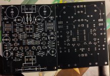
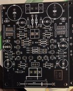
Hmm, the BOM has capacitors up to C10&C11. The boards have C12-C15?
All those(C12-C15) looks to be 100nF footprints like C10&C11.
Is there any reason to stick with X7R rated caps, or would it not be better to put C0G/NP0's there? And the 100nf, would say 220nF C0G/NP0 do(I have all the above, 100nF X7R, 100nF C0G/NP0 and 220nF C0G/NP0)?
Edit: I've got 100nF/50V PPS as well should those be an even better choice.
Attachments
The reason i stayed with the sapphire is its low power draw and simple design.I like that
Looks like you got an earlier version than mine. Downloded it from phonoclone in 2022.Hmm, the BOM has capacitors up to C10&C11. The boards have C12-C15?
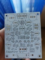
Dont know whos version you got but i couldnt find that layout by RJM.There are some differences between our boards.
Apart from the extra decoupling capacitors, the layout seems identical... unless I'm missing something.Dont know whos version you got but i couldnt find that layout by RJM.
- Home
- Amplifiers
- Headphone Systems
- RJM Audio Sapphire Desktop Headphone Amplifier