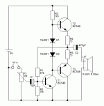
I`m wondering why does 3w @ 4ohm here needs 10v p-p? Clearly I must be missing something, I remember that in school we learned this formula:
W=(V)squared/R. We had an example with car stereo where 12v*12v / 4ohm = 36w * 0.0707 = 25.5wRms... that stands about right for a car stereo... What is the difference here, what am I missing? Is this a topology dependent, efficiency factor?
I like the idea with 8-0-8 transformer, 12v is not really needed, it`s just what I use right now, before the 7805 & 7808 regulators, therefore +10ish v would suit even better.
I will see if I can get 4wire transformer localy to isolate the gnds (I can`t even think of a ground loop anymore :/ ).
Might even choose SMPS for MCU (5v) as I need it on all the time, I might go the EEPROM route later, but this is not even remotely close to the picture at the moment.
Anyway, we can plan the amplfier around +20v, I will make everything else work around it.
We don`t need to worry about a tone control. I will be making active preamp (probably around NE5532, TL072, etc..). I will try to make a divider network and measure original amplifier frequency response with a PC, then I will try to make a preamp with eq curve as close to it (probably it just has large mids boost), followed by active 2 band tone control. I still need to do a research on that.
I see that TDA2003 gets mentioned alot, do you think that it would be worth a try? My concern is that with low power IC amp, it would sound like cheap 90s plastic radio and my plan to boost the mids would drive the thing into distortion really fast.
Looks good and simple to me, but I really don`t have a knowledge to say if its good?Like this one?
But do bridge D1 and D2 with one bigger and clean sounding cap.

Not you, but your ear will say, if it is good;-)
Almost irrelevant in practice.
A Tone control is not necessary, even worsens the sound: more noise, component sound character chaos...: makes the sound dirty and unclean. It is better to install the loudspeaker according to the laws of physics and treat it according to the laws of physics;-)
Paper numbers, paper lines, by and for paper tigers;-)I`m wondering why does 3w @ 4ohm here needs 10v p-p? Clearly I must be missing something, I remember that in school we learned this formula:
W=(V)squared/R. We had an example with car stereo where 12v*12v / 4ohm = 36w * 0.0707 = 25.5wRms... that stands about right for a car stereo... What is the difference here, what am I missing? Is this a topology dependent, efficiency factor?
I like the idea with 8-0-8 transformer, 12v is not really needed, it`s just what I use right now, before the 7805 & 7808 regulators, therefore +10ish v would suit even better.
I will see if I can get 4wire transformer localy to isolate the gnds (I can`t even think of a ground loop anymore :/ ).
Might even choose SMPS for MCU (5v) as I need it on all the time, I might go the EEPROM route later, but this is not even remotely close to the picture at the moment.
Anyway, we can plan the amplfier around +20v, I will make everything else work around it.
We don`t need to worry about a tone control. I will be making active preamp (probably around NE5532, TL072, etc..). I will try to make a divider network and measure original amplifier frequency response with a PC, then I will try to make a preamp with eq curve as close to it (probably it just has large mids boost), followed by active 2 band tone control. I still need to do a research on that.
I see that TDA2003 gets mentioned alot, do you think that it would be worth a try? My concern is that with low power IC amp, it would sound like cheap 90s plastic radio and my plan to boost the mids would drive the thing into distortion really fast.
Almost irrelevant in practice.
A Tone control is not necessary, even worsens the sound: more noise, component sound character chaos...: makes the sound dirty and unclean. It is better to install the loudspeaker according to the laws of physics and treat it according to the laws of physics;-)
Hello, I have a couple diy amplifier modules that could fit,you could have a look here:True that.
I never liked tone controls either, only with subwoofers I used around 60hz boosts...
But project calls for it and I think that it takes a good place in it, because of low power full range speaker.
https://www.ebay.de/usr/rocksandsound
I do have modules with 3 channel and 4 channel but the one using LM4781 is a 3 channel rated at 35 watt rms.
Regards
using the pp output voltage for power calculation is only correct with a bridge amp.What is the difference here, what am I missing?
With a single amp and 10 Vout pp you only get:
(10 V * 0.707 / 2)² / 4 Ohm = 3.1 W
I`m wondering why does 3w @ 4ohm here needs 10v p-p? Clearly I must be missing something, I remember that in school we learned this formula:
W=(V)squared/R. We had an example with car stereo where 12v*12v / 4ohm = 36w * 0.0707 = 25.5wRms... that stands about right for a car stereo... What is the difference here, what am I missing? Is this a topology dependent, efficiency factor?
I like the idea with 8-0-8 transformer, 12v is not really needed, it`s just what I use right now, before the 7805 & 7808 regulators, therefore +10ish v would suit even better.
I will see if I can get 4wire transformer localy to isolate the gnds (I can`t even think of a ground loop anymore :/ ).
Might even choose SMPS for MCU (5v) as I need it on all the time, I might go the EEPROM route later, but this is not even remotely close to the picture at the moment.
Anyway, we can plan the amplfier around +20v, I will make everything else work around it.
We don`t need to worry about a tone control. I will be making active preamp (probably around NE5532, TL072, etc..). I will try to make a divider network and measure original amplifier frequency response with a PC, then I will try to make a preamp with eq curve as close to it (probably it just has large mids boost), followed by active 2 band tone control. I still need to do a research on that.
I see that TDA2003 gets mentioned alot, do you think that it would be worth a try? My concern is that with low power IC amp, it would sound like cheap 90s plastic radio and my plan to boost the mids would drive the thing into distortion really fast.
That’s the kind of fuzzy math that manufacturers use to justify their insane power claims. Which is why I hate powered PA speakers - that’s how it’s calculated and what people think they are getting. The post right above is correct, and what one can realistically expect. Efficiency isn’t really topology dependent, other than how much of the supply voltage gets used. Getting 10V peak to peak out of 12V is as good as it gets. Stuff designed to run on higher voltages generally doesn’t even get that close - losing 3,4 or even 6 volts. It’s just adding up all the voltage drops in saturated transistors, emitter resistors, and whatever else is effectively in series with the load. That original circuit was designed to pull all one can muster out of its limited supply. The TDA2003 would put out slightly less because there is no bootstrapping to allow the driver stage to operate above its rails. But it’s pretty good as chip amps go.
Cheap chip amplifiers sound bad for a couple reasons. Most of them have a LOT of “crossover distortion” due to how the output stage is biased. Advanced ones like LM3886 do better - but the price paid is horrible inefficiency. Proper implementation requires a relatively high split supply. It’s output stops 6 volts short of each rail. On +/-18V, you can only get +/-12V. Then it clips. It won’t even run on on a single 12V supply - at least not well. Most of the output you would get would be distortion. On a single 20V supply, you would only get 8V p-p. Two miserable watts for all the heat produced running off 20V. TDA2003 gets you within 1V of each rail, but does distort more. It tackles the crossover distortion problem by cheating - the application circuit has a sneak path to bias the NPN upper transistor slightly into class A. It then switches to class B at a higher power (only a few mW), but by then it’s less objectionable and most people just won’t notice it.
The very limited power one usually gets in most chip amps is only part of it. Watts is watts, for the most part. But the applications usually call for the smallest (ie cheapest) possible coupling caps which start the low end roll off well into the lower midrange. Couple that with an otherwise “flat” amplifier response and an unbaffled speaker which is also rolling off and you get a thin, tinny, what people call a “transistor” sound. If you can get sufficient undistorted power, have an amplifier that can deliver it at low frequency, and at least SOMEWHERE implement the intentional response shaping that was used, you might be getting somewhere.
Back in the days of tubes, small amplifiers used in these applications invariably had a high output impedance. The natural response that a single driver loudspeaker had with an otherwise flat (but high z) amp was quite pleasing. Not hi fi, but just pleasant to listen to. Chip amps (like TDA2003j can be strapped into transconductance mode and duplicate this almost exactly. No one ever did for anything other than guitar amplifiers. It’s a shame really, because it wouldn’t have given the chip revolution the black eye that it did get when the LM380 was all the rage and small radios and phonographs sounded like complete $#1+.
Ok, more things are clear to me again. Now I also know the math behind insanely overadvertised products. Same with car amplifiers... "500wRms" and a 20a fuse at the back...
Thats my fear... that tinny "transistor sound" if I use the IC.
@cumbb is this amplifier ready to run at 20v as is (your last comment taken into account)?
BD441 instead of BC548 and BD442 instead of BC558 at the power stage; and the other one stays BC548?
I`m just making sure I understand correctly...
I would build the amp on perfboard first, but surely I could try to use SMD anyway.
Thank you for the effort. This looks good to me. The store is closed till Monday as we have holyday today and tomorrow, but on Monday I will try to gather all the parts... I`m affraid that they might not have MJE15030 & 31. Can this be substituted with anything else if needed?
Do you know it`s input impedance? Is it equal to an impedance of C3?
Do you know it`s input impedance? Is it equal to an impedance of C3?
Input impedance is 50k (two 100k parallel equivalent). The cap is a short to audio.
You will need 18-20 V to get 3W - you need the full 16V at load. D44/D45H will work. You need trannies with high(er) gain than TIPs or BD’s.
IF you use low speed low gain junko transistors (ie, all you can get) run them in CFP with a pair of 2N3904/6, MPSA06/56, BC237/337, etc. and you will get substantially the same result.
5532 op amp can be used too. LF351 does not have enough output current, unless the CFP follower approach is used. If you do that the 1k to ground can go to 4.7 or 10k, to reduce heating in the op amp.
cumbb is a troll even his name suggests that CUMbb, also his profile picture is questionable.Ok, more things are clear to me again. Now I also know the math behind insanely overadvertised products. Same with car amplifiers... "500wRms" and a 20a fuse at the back...
Thats my fear... that tinny "transistor sound" if I use the IC.
@cumbb is this amplifier ready to run at 20v as is (your last comment taken into account)?
BD441 instead of BC548 and BD442 instead of BC558 at the power stage; and the other one stays BC548?
I`m just making sure I understand correctly...
I would build the amp on perfboard first, but surely I could try to use SMD anyway.
I see no problem.Ok, more things are clear to me again. Now I also know the math behind insanely overadvertised products. Same with car amplifiers... "500wRms" and a 20a fuse at the back...
Thats my fear... that tinny "transistor sound" if I use the IC.
@cumbb is this amplifier ready to run at 20v as is (your last comment taken into account)?
BD441 instead of BC548 and BD442 instead of BC558 at the power stage; and the other one stays BC548?
I`m just making sure I understand correctly...
I would build the amp on perfboard first, but surely I could try to use SMD anyway.
10 ohm emitter resistors are A Bad Idea and you know it. The basic circuit idea will work. That particular implementation is terrible, even with BD441/2. You could shoehorn the BD441/2, a pair of 1/2 ohm emitter resistors, and the two bias diodes into the original amplifier circuit and yield much better results.
Ge transistors like AC187/8 or 180/181K are perfectly suited to the task, and they naturally swing almost rail to rail:
Amplifiers I made 50 yrs ago sounded quite right for the day
The schematic at post #1 does not seems to be the best one to start. To recreate a circuit, the schematic shoud not have proprietary or hard to find parts such as thermistors; voltages and bias currents should be clearly specified. You will find about a thousand schematics with the AC187/AC188 transistor pair at the radiomuseum.org web site. Search the AC187 transistor. Scroll down to the "usage in models" section and click on a year. This transistor has been popular in 1968 and 1969, so I browsed trough that years results. Tape players often have a better audio section, so I searched for...
That sort of thing will work, but bump the supply up a bit to live with the extra 2 vbe of losses, and use BD441/2 outputs. This is one place where they are exactly what you want. Tie Q2’s emitter to Q1’s collector and put in 0.22 ohm to the output. Same on the PNP side. For thermal run away safety. You may get lucky without the resistors. You may not, and regret it.
- Home
- Amplifiers
- Solid State
- Amplifier suggestion for old 3w speaker