@wg_ski
Allow me to make an interim comment here:
Unfortunately, we do not know the individual parameters of the two combined transistors, only how they are work together as one pice. We can actually assume that the first transistor of the entire Darlington fulfills all the requirements placed on it.
With regard to the present circuit (with its dimensioning), the question arises as to whether this wish has been sufficiently taken into account.
regards,
HBt.
Allow me to make an interim comment here:
Unfortunately, we do not know the individual parameters of the two combined transistors, only how they are work together as one pice. We can actually assume that the first transistor of the entire Darlington fulfills all the requirements placed on it.
Would you like to shed some light on this and explain (the why) in a few sentences?The whole output stage is better behaved if the drivers are faster than the outputs.
With regard to the present circuit (with its dimensioning), the question arises as to whether this wish has been sufficiently taken into account.
regards,
HBt.

Darlington transistors like these are MONOLITHIC. The two transistors are on the same PROCESS. If the output device is on a low fT process so is the driver. They do not make them with a 4 MHz epi-base output and a 100 MHz planar-type driver. And that is what is needed to get fast charge suckout. And a different arrangement of the base-emitter resistors. The faster the charge suckout from the output transistor’s base, the less crossover distortion is produced. That and a sustained-beta driver helps a lot because it will STAY at a flat 100-ish, even when the output has fallen from 250 to 20. If the driver also has the same excursion, composite linearity is that much worse.
Not every self-builder will be aware of this, but it is the crux of the matter - thank you for writing this clearly here.
However, the crucial question that remains unanswered is whether the use of a monolithically integrated Darlington, for example the TIP142/147, is fundamentally bad. We know that a discretely implemented EF2 gives us various degrees of freedom. Or even the famous triple.
It is therefore a conscious decision that may have been made for reasons of convenience, laziness or even ignorance. Maybe cost issues?!
On a closer inspection, the criticism is also justified retrospectively for the year 1979.
#
However, none of this makes this weird amplifier (basically) a bad audio representative. Of course, one can't compare him to Wolverine, nor should one.
HBt.
A Ft=4MHz transistor would not be bad in a class A amplifier with low to moderate global feedback.
Class AB introduces the problem that the transistors cut-off. This is (non-linear) switching rather than (linear) frequency. Slow is bad.
Darlingtons are especially bad because both the driver and output transistors cut-off. With discrete EF2 or EF3, one can keep the driver transistor always on.
Ed
Class AB introduces the problem that the transistors cut-off. This is (non-linear) switching rather than (linear) frequency. Slow is bad.
Darlingtons are especially bad because both the driver and output transistors cut-off. With discrete EF2 or EF3, one can keep the driver transistor always on.
Ed
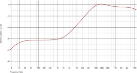
They say that the PSU noise is at -110dB at the amp output, yet here its simulated PSRR, by all standards
that s even worse than singleton IPS based amps, @wg_ski mentioned several elephants in the room, look like
it s litteraly a herd of mammoths.
that s even worse than singleton IPS based amps, @wg_ski mentioned several elephants in the room, look like
it s litteraly a herd of mammoths.
Attachments
However, the crucial question that remains unanswered is whether the use of a monolithically integrated Darlington, for example the TIP142/147, is fundamentally bad. We know that a discretely implemented EF2 gives us various degrees of freedom. Or even the famous triple.
It is therefore a conscious decision that may have been made for reasons of convenience, laziness or even ignorance. Maybe cost issues?!
Fundamentally bad? Not necessarily, but fundamentally worse than the equivalent amount of silicon would be if it were more optimally arranged and selected. Not necessarily any cheaper either, other than ASSEMBLY costs.
It’s just “pressing the easy button”, and getting the compromises that come with it. One can get better performance with the Sanken darlingtons, which are monolithic of epitaxial planar 30-ish MHz construction (giving composite fT of 60 to 80). But you’re still stuck with the Rbe in the wrong place, and could do better with their separate outputs and driver.
Speaking of class B (or AB) representatives:
Other top-class developers also use the inexpensive Darlington TIP142/147, they know about the blessings of the parallel outputstage /circuit.
Nelson Pass AB100
Other top-class developers also use the inexpensive Darlington TIP142/147, they know about the blessings of the parallel outputstage /circuit.
Nelson Pass AB100
Pass s amp use 4 pairs, that s 1.25A/pair/8R and 2.5A/4R, we are far from ETI who use a single pair for 60W/8R.
Exactly - in the end one have to decide whether one want a Darlington or a genuine, discrete EF2. If we opt for the integrated Darlington, then we have to accept the resulting peculiarities and consequences.Pass s amp use 4 pairs, that s 1.25A/pair/8R and 2.5A/4R, we are far from ETI who use a single pair for 60W/8R.
Connect in parallel and keep it nice and cool, but watch out for wild oscillations tendency.
#
Perhaps we should consider circuits with the TIP142/147 more as EF1? Then we would no longer be in danger of making a comparison with the classic EF2 as a blameless OPS.
And as long as the THD remains below 0.03%, its curve is flat and the distortion spectrum is acceptable, there is no reason to complain. If our product is practical and suitable, then "sponge over it", right?
HBt.
I find it difficult to categorize your simulation result.They say that the PSU noise is at -110dB at the amp output, yet here its simulated PSRR, by all standards
that s even worse than singleton IPS based amps, @wg_ski mentioned several elephants in the room, look like
it s litteraly a herd of mammoths.
If we assume that the originators did not make a measurement error, then there is a very large gap between their characteristic value and your function graph.
"Hum and Noise: better than -110dB on full output (dependent o psu)", we read!
But what does that mean? 2.74A_rms load current leads to a theoretical* hum voltage of 5.48V with (recommended) 5mF charging capacitors. The DC operating voltage is +/-40V of the rails. We estimate the total resulting internal resistance of the power supply to be no greater than 2 ohms.
Considered as a regulator, a sufficiently large control difference remains, i.e. the regulator can potentially achieve a sufficient PSSR.
-110dB sounds far too good to be true. Without additional information on this specified value, you can do absolutely nothing with it. At most, it signals that the expected signal-to-noise ratio will be usable.
* In reality, this voltage is much lower
At the end of the day,
this means it doesn't really matter. "It's not important!"
The -110dB value should be interpreted as what it is:
the averaged noise & hum voltage (on the output side) without load and with short-circuited input, related to the maximum possible output voltage of the amplifier, i.e. 22V_rms.
greetings,
HBt.
the averaged noise & hum voltage (on the output side) without load and with short-circuited input, related to the maximum possible output voltage of the amplifier, i.e. 22V_rms.
- to indirectly deduce the PSRR of the amplifier as a controller, let's say at 100Hz ripple -> 20* log_10(70µV/5.5V) -> -98dB
- a pure voltage specification of perhaps 0.8mV_rms is realistic, typical for a 50Watt representative of the time -> would therefore be -77dB and not -110dB!
greetings,
HBt.
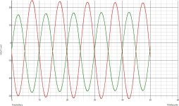
There s no mistake, here a transient simulation with 1V pk 100Hz injected in each rail, the red curve is with ripples
of each rail being in opposite phase and wich is the case that interest us, in green that s with the two ripples being
in phase just for info, input is of course shorted to the ground.
The RMS values are 19mV and 15.8mV respectively, the RMS value of the ripples being 0.707V this amount to -31.4dB,
exactly what is displayed at 100Hz in the frequency domain simulation.
They surely used a regulated PSU for the tests, otherwise they couldnt even have measured the amp noise,
anyway that s yet another elephant in an already crowded room, but beyond the irony it means that this amp
is not even Hifi unless there s no output signal, or very few, and that the PSU noise is something like 0.1V/rail.
Attachments
... based on the full load operation of 60W, this would be comparable to an SNR of better than 60dB (in this case). So the hi-fi loudspeaker is flying around our ears, but we are bothered by 20mV_rms 100Hz hum at 8 ohms. All at the same time.The RMS values are 19mV and 15.8mV respectively, the RMS value of the ripples being 0.707V this amount to -31.4dB,
exactly what is displayed at 100Hz in the frequency domain simulation.
Let's just take a look at this point of the statement and ask ourselves: how do we make the ETI-470 proposal suitable for hi-fi?but beyond the irony it means that this amp
is not even Hifi unless there s no output signal, or very few, and that the PSU noise is something like 0.1V/rail.
Can we modify the two visible current sources so that something decent comes out? How?
#
We know that the amplifier will dynamically draw a time- and load-dependent current from the power supply unit. This current will modulate the rail!
If our power supply were an ideal DC voltage source, we wouldn't worry about the momentary pickup at all - the Ripper. There would be no disturbing ripple-voltage.
HBt.

We have therefore identified a weakpoint that can be solved very quickly in order to significantly improve the basic circuit (of this amplifier).
Any suggestions?
Any suggestions?
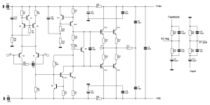

Consequently, we are replacing the TIP142/147 Darlington with the classic EF2.
But now we have to be very careful that the 20WPA doesn't mutate into Douglas Self's BLAMELESS amplifier.
greetings,
HBt.
🧙♂️
But now we have to be very careful that the 20WPA doesn't mutate into Douglas Self's BLAMELESS amplifier.
greetings,
HBt.
🧙♂️
Attachments

- Home
- Amplifiers
- Solid State
- 20WPA