Just another brain streams about circuit per above;
A) PS voltage for input LTP can be made very low, like +- 5V in order to keep heat dissipation under control for high bias currents. Likely PS voltage for opamps can be at high limit (eg +-20V) to keep overload margin high.
B) Opamp needs to drive feedback network (1kR in Hans's diagram) and RIAA network. In both cases lower impedance will be better, however we cant oveload opamp neither, particularly if very high gain=high HF voltage is expected at their output. I am just considering jellybean NJM4580 in this function as except of decently low noise, that opamp has unbeatable high output current capability.....
A 0.35mV@1Khz Cart produces with Riaa ca. 3mV@10kHz.It seems that you used 10mV as input signal?
Giving it a 10dB extra overload margin gives 10mV@10kHz, that’s why.
Input noise has no relation to input voltage, but with 0.35mV@1kHz and 74nV input noise, result is a 73dB S/N including the 10R Cart.
This S/N will be further improved by Riaa and A-Weighting.
I will repeat the sim for a 40R Cart while keeping the gain at 46dB.
Hans
P.s. with 1K resistors and output below 1Volt, opamp has to deliver 1mA, so why the need for a high output current op-amp ?
Here are the results with a 40R Cart, still using 46dB gain.
THD with 10mV@10kHz is now even (unrealistically) lower, and noise has risen to 126nV or 0.89nV/rtHz including 40R cart.
S/N is now 20*Log(0.35mV@1kHz/126nV) is 69dB, still very good.
Hans

THD with 10mV@10kHz is now even (unrealistically) lower, and noise has risen to 126nV or 0.89nV/rtHz including 40R cart.
S/N is now 20*Log(0.35mV@1kHz/126nV) is 69dB, still very good.
Hans

Dear Hans,
Before Hierfi was doing research in this direction and also I can confirm that my 20years 2x 60db gain front amp (gain before RIAA) never show any issue.
P.S., with dropping needle on record and hard scratches I have no issue, they can clip if they like, they are ugly with or without clipping 🙂
I am still puzzled if this 10db margin in HF region is actually ever needed. I read old Shure documents on V max output vs frequency from LP, there it is not concern As soon as I have possibility Ill run few hours test capturing maximum levels of several LP's just to confirm it for myself at least.Giving it a 10dB extra overload margin gives 10mV@10kHz, that’s why.
Before Hierfi was doing research in this direction and also I can confirm that my 20years 2x 60db gain front amp (gain before RIAA) never show any issue.
P.S., with dropping needle on record and hard scratches I have no issue, they can clip if they like, they are ugly with or without clipping 🙂
It was just my brain stream and I'm considering also lower Z carts, like my friend have ZYX R50 Exceed Bloom at only 4 ohm internal Z. If we want to keep 46db gain, Rf will become 400 ohms for this cart and we additionally load it with RIAA filter. As I said it is just contemplation, with wish to cover both ends of MC cartridges varieties in good way....P.s. with 1K resistors and output below 1Volt, opamp has to deliver 1mA, so why the need for a high output current op-amp ?
Thanks Hans, looks really promising . I will build this prototype as soon as I manage time. I have some ZTX's and different opamps to put in....Here are the results with a 40R Cart, still using 46dB gain.
THD with 10mV@10kHz is now even (unrealistically) lower, and noise has risen to 126nV or 0.89nV/rtHz including 40R cart.
S/N is now 20*Log(0.35mV@1kHz/126nV) is 69dB, still very good.
Hans
View attachment 1357571
I remember your post. The question is why change and move on when noise performance is already verifiably low... perhaps low enough for your application? What about the sonics is expected being "fine tuned" other than noise?Hi Hierfi,
I can confirm that circuit you draw is very good, excellent actually!. It is qualified by more than 20 years of use 🤣
That is exactly my original preamp posted at beginning of this thread https://www.diyaudio.com/community/...ono-preamplifier-thoughts.414816/post-7731430
View attachment 1357534
However good they are, SSm2017-9 are tuned as mic preamp and microphones normally have much higher Z than MC carts . By rconstructing the model we can fine tune it with better input transistors and higher bias currents as Hans just did 🙂
The SSM2017-9'S may have their main application in mic preamps but aren't tuned before the value of the gain setting resistor is decided upon, with the value of resistance strongly determinant of noise performance. For moving coils the gain needs to be set to the highest possible for lowest noise. Certainly the noise performance is adequate in current mode using a single device when using a Denon 103r.
Last edited:
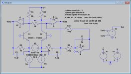
The reason I suggested this could be problematic is because the DC operating points could vary dramatically with tolerance variations. How do input offset voltages of op-amps get corrected? What is the value of the output voltages in balance? It seems at the very least that creating signals about 0 volts can require some attention.I simulated just a possible version of the circuit as a transimpedance amp with Rcart=10R and diff. gain of 46dB.
The two Opamps where ordinary 5nV/rtHz versions but the transistors the very low noise ZTX851 with 5mA feeding them.
THD with 10Khz@10mV and the gain of 46dB was -135dB, while noise from 20Hz to 20Khz was 74nV or 520pV/rtHz, which is all very good.
Hans
View attachment 1357505
In contrast an integrated package like the SSM2019 seems having internals perhaps laser trimmed with cross-coupled thermal tracking internally. It does a very good job of DC control, hence a trimming potentiometer seems all that is needed in it.
Last edited:
Hi Hierfi,I remember your post. The question is why change and move on when noise performance is already verifiably low... perhaps low enough for your application? What about the sonics is expected being "fine tuned" other than noise?
Well, answer is multi-fold: First as I am rebuilding my TT, I thought it is good idea to revisit very old preamp design that I made based on reading datasheets, pen and paper mathematics and guts. Then friend here on forum told me that my precious Ruby cart deserves much better preamp than what I made and use, well that triggered a bit of pride and I wanted to dig deeper.
Finally, and for me most important: I have seen many phono preamps designs, but very few utilizing fully balanced floating source characteristic of cartridge. It is my curiosity why is that as I see humongous benefits in this approach. We discussed it at beginning of thread and I think in pst #153 I showed -80db rejection of common mode noise for SSM2017. Still think that is respectable benefit especially since cart is floating in the air and suspected to pick up any signal (noise) around and overcomes small noise penalty of 1.41 dictated by source seeing 2 transistors in series instead of 1.
It is excellent chat in my opinion, and good use of free time , think it will also trigger better designs by other members who are reading it...🙂
Hi, I think we should be able to overcome this with matching transistors, 0,05% resistors and might be some of xxx27 or xxx37 opamps that are both low noise and DC accurate. Besides, output will see RIAA network as load, passive RIAA cares not about DC that can be removed in second stage.In contrast an integrated package like the SSM2019 seems having internals perhaps laser trimmed with cross-coupled thermal tracking internally. It does a very good job of DC control, hence a trimming potentiometer seems all that is needed in it.
A 0.35mV@1Khz Cart produces with Riaa ca. 3mV@10kHz.
Giving it a 10dB extra overload margin gives 10mV@10kHz, that’s why.
As indicated I conducted some experiments with the gain of the SSM2019 set to produce 4V RMS at 1 KHz 5 cm/sec., corresponding to about +/- 5.6 Volts pk/pk. The power supplies began clipping at +/-7.5 Volts, giving about a 2.5dB overload margin. The listening tests involved listening to material while observing the clipping on an oscilloscope.I am still puzzled if this 10db margin in HF region is actually ever needed. I read old Shure documents on V max output vs frequency from LP, there it is not concern As soon as I have possibility Ill run few hours test capturing maximum levels of several LP's just to confirm it for myself at least.
Before Hierfi was doing research in this direction and also I can confirm that my 20years 2x 60db gain front amp (gain before RIAA) never show any issue.
On recordings containing regular clipping occurring on high frequency transient type material (a function of being recorded in inverse RIAA), clipping only occurred with high rate of rise/fall signals going into and out of clipping, oftentimes with 50uSec to 100uSec clipping periods. Although clipping was visible there was no edginess being detected as a result, with seeming an anomalous character only barely noticeable. It should be noted that harmonics created from clipping are subsequently rolled off by the RIAA, and those harmonics created from clipping seem likely above the most sensitive region of human hearing. In other words more innocuous sinusoidal reduction of the amplitudes of transients.
Although the clipping was questionably audible, I ended up reducing gain in half as a safeguard, setting this at 2 V RMS for 1kHz/ 5 cm/sec. In other words adding about 6dB to the 2.5dB or about an 8.5dB overload margin, effectively the same as Hans at 10dB.
Headroom above 10dB (or about x3 above the 1kHz/5cm), often suggested as highly significant as the higher the better, has little if any merit in amplification pre-RIAA. It also can mean gaining sonic benefit by pushing signal level gain to this maximum to improve signal to noise ratios, either internal to the SSM2019 or subsequently in feeding higher level signals to the RIAA network.
The main problem appears that difference signals on the inputs of the opamps are magnified by the open loop gain of the xxx27/37 devices, if that is what is being used. Lets say the offset is 100uV with open loop gain of 120dB. If one device has zero offset and the other 100uV the average is 50uV (50uV neither wants to see), creating 50 V of differential output offset after the gain of 1 million. That's beyond the power supply limits. Basically you have 2 devices fighting each other for supremacy using their open loop gain to do this.Hi, I think we should be able to overcome this with matching transistors, 0,05% resistors and might be some of xxx27 or xxx37 opamps that are both low noise and DC accurate. Besides, output will see RIAA network as load, passive RIAA cares not about DC that can be removed in second stage.
Last edited:
👍 Similar is my thinking, just I take 20kHz as reference, which is x10 more V, and than I take no margin, pls see next post.Headroom above 10dB (or about x3 above the 1kHz/5cm), often suggested as highly significant as the higher the better, has little if any merit in amplification pre-RIAA. It also can mean gaining sonic benefit by pushing signal level gain to this maximum to improve signal to noise ratios, either internal to the SSM2019 or subsequently in feeding higher level signals to the RIAA network.
Let me some time run some records, I also want to see it for myself..
Hi, not sure if I understood you right on this one:As indicated I conducted some experiments with the gain of the SSM2019 set to produce 4V RMS at 1 KHz 5 cm/sec., corresponding to about +/- 5.6 Volts pk/pk. The power supplies began clipping at +/-7.5 Volts, giving about a 2.5dB overload margin. The listening tests involved listening to material while observing the clipping on an oscilloscope.
A) we are talking pre RIAA EQ, correct? If yes than 4VRMS @ 1kHz will be +20db @ 20kHz, equals 40VRMS for 0db signal. That's high even for my taste, even there is hardly to observe any 0db signal at 20kHz ( we would be in hospital if someone recorded 20kHz at 0db)
B) we can run chips at +-18V for instance. as I run SSM2017 in original preamp, not much in decibels but allows for some extra margin before clipping.
I understand your concerns, and yes the SSM is an fine component to use, ready to go.The reason I suggested this could be problematic is because the DC operating points could vary dramatically with tolerance variations. How do input offset voltages of op-amps get corrected? What is the value of the output voltages in balance? It seems at the very least that creating signals about 0 volts can require some attention.
In contrast an integrated package like the SSM2019 seems having internals perhaps laser trimmed with cross-coupled thermal tracking internally. It does a very good job of DC control, hence a trimming potentiometer seems all that is needed in it.
Nevertheless, it's sometimes challenging to look over the fence looking for possible alternatives.
And for almost every problem there is a solution, in this case to compensate offset voltages.
A servos will do the job, without affecting noise, Frequency response or causing unacceptable currents from flowing through the Cart.
I'm not defending any solution, just showing what can be done to overcome a possible problem.
In this example with the given servo components, +/-4mV offset can be compensated, a dual opamp like the OPA1656 or even an NE5532 will fit.
A dual servo on both sides is the most accurate but even a single one is already very effective, see attachment.
And yes, the collector and feedback resistances should be tightly matched, not a real problem.
Hans
Attachments
Luckily here i have bit more, even still modest, experience. In the past I used OP27-37 and TLE2027 quite a bit. These have DC offset in average about 5uV, 100uV you mentioned is extreme limit of specifications. Additionally they also (all of them) have offset trim pins that if someone has nerves and time to measure nV DC offsets, can be brought to virtual 0 DC offset.The main problem appears that difference signals on the inputs of the opamps are magnified by the open loop gain of the xxx27/37 devices, if that is what is being used. Lets say the offset is 100uV with open loop gain of 120dB. If one device has zero offset and the other 100uV the average is 50uV (50uV neither wants to see), creating 50 V of differential output offset after the gain of 1 million. That's beyond the power supply limits. Basically you have 2 devices fighting each other for supremacy using their open loop gain to do this.
Hereby I mentioned just vintage opamps that I am more familiar with, quite confident there will be more contemporary chips with those characteristics, and hopefully better sound.
Kind regards,
Dražen
Valuable thought!I understand your concerns, and yes the SSM is an fine component to use, ready to go.
Nevertheless, it's sometimes challenging to look over the fence looking for possible alternatives.
And for almost every problem there is a solution, in this case to compensate offset voltages.
This is likely better than trim pots solution.A servos will do the job, without affecting noise, Frequency response or causing unacceptable currents from flowing through the Cart.
I'm not defending any solution, just showing what can be done to overcome a possible problem.
In this example with the given servo components, +/-4mV offset can be compensated, a dual opamp like the OPA1656 or even an NE5532 will fit.
A dual servo on both sides is the most accurate but even a single one is already very effective, see attachment.
And yes, the collector and feedback resistances should be tightly matched, not a real problem.
What do you suggest for U3 and U4 servo amps, just that I have them in drawer when assembling time comes. Guess some jfet input precision opamps ?
No need for precision opamps, they will reduce the output voltage to within their own offset voltage.What do you suggest for U3 and U4 servo amps, just that I have them in drawer when assembling time comes. Guess some jfet input precision opamps ?
But because of the 1Meg input resistor, fet opamps should be used.
All dual fet opamps with offsets below a few mV will do, there are several to choose from, speed or noise are unimportant parameters.
Hans
One thing I own, last month I always excused myself that I'm on holidays fishing, well, there was not so much fish as season was still to early, nevertheless there was one tasty piece and I share picture of me with beauty with you.
Now again I need to drop preamp issue for few days as TT motor project seems to go in good way, I need to clean my work desk and bring actual TT on it, it is huge and will eat most of desk space, tidy up time is necessary...,

Now again I need to drop preamp issue for few days as TT motor project seems to go in good way, I need to clean my work desk and bring actual TT on it, it is huge and will eat most of desk space, tidy up time is necessary...,
Dear Hans, so what you say old and so much undermined TL072 will do , especially if cherry picked for low offset V?All dual fet opamps with offsets below a few mV will do, there are several to choose from, speed or noise are unimportant parameters.
That's a perfect opamp for the job.so what you say old and so much undermined TL072 will do , especially if cherry picked for low offset V?
And congrats with the beautiful Fish that you captured, hope it tasted just as well.
Hans
Oh yes, I always let go back to the sea everything that is not to damaged to live on, or if it is too tasty, than problem is my greed.. This fish had bad fortune that is just too good to eat, this is her body before dismissal into my digestion system:And congrats with the beautiful Fish that you captured, hope it tasted just as well.
- Home
- Source & Line
- Analogue Source
- Fully balanced MC phono preamplifier thoughts