Yeah the pattern is limited on the top end to this ,where sound gets directional. Luckily bulk of the box makes the pattern up there so one could slide the back port radiation lower in frequency, and try to find balance for these off-axis "issues". But not too low, here is an example:
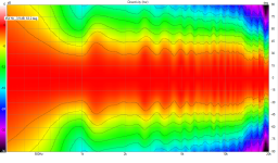
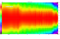
Here is my old measurement of the 8" mid alone, normalized, I've likely posted this in this thread already. Scale of the graph is adjusted to really show off-axis radiation problem around 600-1000Hz. Problem is actually at longer than box size wavelength. It's still -10db down or so on the red off-axis region, but looks bad right?

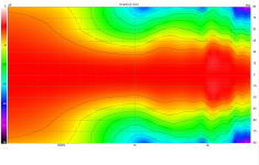
Just for fun, I can make this "problem" go away from exact same data just by scaling the graph suitably 😀 So, mind the scale when evaluating performance.

Nice pattern between about 100-600Hz, about 2.5octaves. Or how ever one wants to analyze the graph. Bandwidth for this unit in 3-way speaker application is about 200 - 1500Hz so the pattern is not optimal, I'd need the good pattern shifted by an octave up. Sound is just fine though so perhaps not too critical, but i'd like the graphs to be better,. Perhaps it would have meaningful effect on sound to have as uniform response as posible, as I'm using these near front wall.
Here is my old measurement of the 8" mid alone, normalized, I've likely posted this in this thread already. Scale of the graph is adjusted to really show off-axis radiation problem around 600-1000Hz. Problem is actually at longer than box size wavelength. It's still -10db down or so on the red off-axis region, but looks bad right?
Just for fun, I can make this "problem" go away from exact same data just by scaling the graph suitably 😀 So, mind the scale when evaluating performance.
Nice pattern between about 100-600Hz, about 2.5octaves. Or how ever one wants to analyze the graph. Bandwidth for this unit in 3-way speaker application is about 200 - 1500Hz so the pattern is not optimal, I'd need the good pattern shifted by an octave up. Sound is just fine though so perhaps not too critical, but i'd like the graphs to be better,. Perhaps it would have meaningful effect on sound to have as uniform response as posible, as I'm using these near front wall.
Last edited:

Nice to read all these good comments, it is great to share knowledge and experience.
So I did another experiment to learn and measure other directivity pattern.
Once again, it is not perfect and my wife who is off today is quite mad at me...
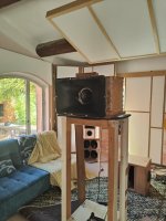
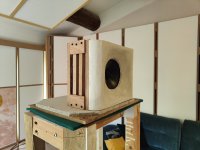
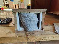
But the Idea was to measure a JBL midhorn from a Cinema Series. There is the PHL driver without the phase plug that can be found on CMCD drivers.
The result is a narrow medium and the control in the lower section is not that good.
But I had do dismount the PHL from the other baffle to redo the vents. Next week I will create a bigger hole which will be partially covered with wood sticks to try different position and surface. I noticed that I forgot to put felt behind the driver...
So I did another experiment to learn and measure other directivity pattern.
Once again, it is not perfect and my wife who is off today is quite mad at me...
But the Idea was to measure a JBL midhorn from a Cinema Series. There is the PHL driver without the phase plug that can be found on CMCD drivers.
The result is a narrow medium and the control in the lower section is not that good.
But I had do dismount the PHL from the other baffle to redo the vents. Next week I will create a bigger hole which will be partially covered with wood sticks to try different position and surface. I noticed that I forgot to put felt behind the driver...
Attachments
The manta has a trapezoidal array of slits. Why so, I wonder. Perhaps it is shaping the side radiation directivity intentionally.
Amphion Krypton have same kind of trapezoidal arrangement ( but perforated). Krypton follow the shape of internal boxe which is trapezoidal. At first sight i said to myself they had an issue with inside box reflection, but it could be something else.
The small rectangular boxes are rather cheap and fast to make, perhaps prototype. I think kimmosto cardioid boxes also had multiple narrow slots on side panels, from front to back.
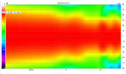
I thin kgood goal for the patrern is to have it as uniform as possible, not a ridge off-axis like I have currently, and preferably ~20db off attenuation to really knock down interference from wall behind. Although, biggest dip in the miidrange, measured from listening spot, is floor and ceiling reflection, so not sure how much difference ot makes whether the attenuation is 10db or 20db.
Btw, on the lower picture DI trend is visible, it's not flat on the pass band but sloping up a bit. This is mostly due to narro baffle without any roundover, and main diffraction hump narrows the pattern few db, compared to bit wider baffle and some roundover. This is evident in simple omni vcad diffraction sim. Also, so far quite little mentioned effect, with woofer that has dust cap Sd is not same front and back, which is responsible of not that good cancellation overall. Use woofer with phase plug, ot a coax, to equalize Sd both sides of the cone. This is easy test in ABEC, just move dustcap mesh from the source definition to external domain.
Last edited:
Tmuikku,
So do you finally think that the box should be a little bit deeper ?
What is the kimmosto design ?
I did a baffle which ressembles yours thanks to your posts and we seem to have the same problem in the mids.
I think the thin and long ports or multiple small holes create a good low pass filter. The idea behind, I think, is that the higher the frequency, the more stochastic the response is and therefore the cancellation is pretty not homogeneous. But directivity at higher frequency is created by the front baffle and the speaker.
He did an awful lot of research on passive and active cardioid systems.I think kimmosto cardioid boxes also had multiple narrow slots on side panels, from front to back.
I can also see why he put that offline.
If Kimmo decided to take everything off the internet, we should respect imho.
Otherwise check your pm, i'm finally availlable this week end, we could have a phone call.
Tu es bien matinal! 😉
'You are an early bird! 😉 '
Otherwise check your pm, i'm finally availlable this week end, we could have a phone call.
Tu es bien matinal! 😉
'You are an early bird! 😉 '
Last edited:
OK,
I also found the Directiva Project on ASR which is open source and promising. The medium box looks like the box I will try this week...
https://www.audiosciencereview.com/...ctiva-r2-monitor-prototype-build.30132/page-3

I also found the Directiva Project on ASR which is open source and promising. The medium box looks like the box I will try this week...
https://www.audiosciencereview.com/...ctiva-r2-monitor-prototype-build.30132/page-3
Hi, deep box certainly changes things, I just need mine small. You can play with outside and inside dimensions separately.Tmuikku,
So do you finally think that the box should be a little bit deeper ?
What is the kimmosto design ?
I did a baffle which ressembles yours thanks to your posts and we seem to have the same problem in the mids.
I think the thin and long ports or multiple small holes create a good low pass filter. The idea behind, I think, is that the higher the frequency, the more stochastic the response is and therefore the cancellation is pretty not homogeneous. But directivity at higher frequency is created by the front baffle and the speaker.
OK,
I did run a quick test as it was intriguing me...
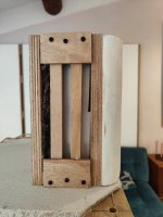
I just removed the sides and put 2 thin peaces of wood to have 3 slots. I took the opportunity to put some kind of recycled textile we buy to protect the floor when we paint. Melamine sponges on the bottom the top and the sides.
Then I run Some sweeps from 1m with 4ms gating
You can download the rew files here if you want : (phl cardio 2 mdat)
https://drive.google.com/drive/folders/1AWzq2e-I7cqv6NSKWMpLhJUMNxPU30GH?usp=sharing
The results is much cleaner than in earlier version, the problem at 1.2 khz is no longer here.
I did run a quick test as it was intriguing me...
I just removed the sides and put 2 thin peaces of wood to have 3 slots. I took the opportunity to put some kind of recycled textile we buy to protect the floor when we paint. Melamine sponges on the bottom the top and the sides.
Then I run Some sweeps from 1m with 4ms gating
You can download the rew files here if you want : (phl cardio 2 mdat)
https://drive.google.com/drive/folders/1AWzq2e-I7cqv6NSKWMpLhJUMNxPU30GH?usp=sharing
The results is much cleaner than in earlier version, the problem at 1.2 khz is no longer here.
Attachments

Yes it's better. You could maybe try/investigate to have the octave between 700/1,5khz smoother.
It's actually not that difficult and just requires toying around with VituixCAD to find good combinations of filters.With an active cardioid, you have more options, you can shape the phase and magnitude with frequency. You can do more than try various thicknesses of various kinds of absorbers. I'm sure Kii has mastered that trick; I'm starting to get a feel for it.
Crossover for the speaker above:
Simulations in VituixCAD match up pretty well with measurements of the complete system.
For the next project I'd like to use a coaxial driver and either four woofers on all sides or slots on all sides so the floor and ceiling reflection would also be attenuated.
Four woofers would increase the output capability greatly, but there are B&C coaxials that might just be powerful enough to do it with one driver and slots.
floor and ceiling first specular reflections in ~2.5m high room and ~1m listening height are about 20-50deg, so cardioid has hardly any effect on those. Open baffle / dipole has some, waveguides/horns could have some and arrays the most.
I'm glad to hear that simulations match measurements fairly well because my planned system has passive cardioid coax combined with active cardioid bass. I originally had 4 woofers - 2 dual opposed slot loaded in front and 2 on the sides. That worked quite well in simulation, except the vertical directivity towards the ceiling was unrestricted and led to a ceiling reflection null. This was fixed by adding a 5th woofer on the top rear of the cabinet. The side and top woofers are driven inverted and delayed above 60 Hz and in phase below 60Hz so all add constructively where I need the volume displacement yet give me cardioid like directivity from just below 100 Hz up.
Even though I have said it myself, my current simulations dispute that assertion that cardioid has hardly any effect on boundary nulls. Sure OB allows you to toe in so that a null is thrown at the first reflection point, If you experiment with toe-in and ref angle with cardioid, you can do almost as well.

Even though I have said it myself, my current simulations dispute that assertion that cardioid has hardly any effect on boundary nulls. Sure OB allows you to toe in so that a null is thrown at the first reflection point, If you experiment with toe-in and ref angle with cardioid, you can do almost as well.
My comments about active cardiod are based on the design pictured below where I have 4" drivers on all 4 sides just 153 mm behind the front baffle of a sealed 8" coax (8HX200). This system is cardiod from about 125 Hz up but its directivity isn't quite as deep as the one described above. Nevertheless, its system simulation looks quite good and I'm torn between the two designes. If you look closely at my crossover schematic, you will see a couple of phase EQ blocks. I could not have achieved this performance without them. I question whether I can measure well enough to achieve in practice but the performance potential is there, as Vituix is using ABEC generated directivity. Also still investigating how many FIR taps are needed to pull this off. I'm hoping to fit the XO into a Flex4 per side. The nice thing about getting full range cardioid from the coax plus side woofers is that the sub it sits on is just a simple sealed box. I'm using a pair of Dayton LS10-44 shallow mount subs playing to 125 Hz.


That makes sense in a typical listening room, but with an output of >130dBSPL my speakers aren't exactly built for that.floor and ceiling first specular reflections in ~2.5m high room and ~1m listening height are about 20-50deg, so cardioid has hardly any effect on those. Open baffle / dipole has some, waveguides/horns could have some and arrays the most.
nc535, why not use IIR filters and then correct the phase afterwards? IIR DSPs are much cheaper and you can still use another one with FIR capabilities in front of those.
the schematic will change as I move from design to implementation. I tend to use FIR autoEQ wherever I can because its so easy, espcially for simulation. Then when I run of taps, I have to get to work and see where I can get by with IIR. I avoid IIR for high pass and low pass when doing cardioid because of the phase flips.
.I appreciate the suggestion. I imagine that would work well if I were to try to squeeze this into a Hypex plate amp with limited FIR.
.I appreciate the suggestion. I imagine that would work well if I were to try to squeeze this into a Hypex plate amp with limited FIR.
Hi guys,
My clones are finally finished and have been playing for a week now. And very much to my satisfaction. They sound incredibly good.
Tweeter: Visaton KE25 SC (modified)
Midrange: Visaton AL200
Woofers: 2x Visaton TIW 200XS
DSP: MiniDSP 2x4HD
Power amplifiers: 2x Icepower 125ASX2


My clones are finally finished and have been playing for a week now. And very much to my satisfaction. They sound incredibly good.
Tweeter: Visaton KE25 SC (modified)
Midrange: Visaton AL200
Woofers: 2x Visaton TIW 200XS
DSP: MiniDSP 2x4HD
Power amplifiers: 2x Icepower 125ASX2
- Home
- Loudspeakers
- Multi-Way
- Resistive port cardioid active speaker insipired by D&D 8C