Yes, I understood from the knowledge from this topic that port shall be as close as possible to the front baffle..but my front baffle is a waveguide so I can't go closer...
I will do that test from behind, it is clever.
I will do that test from behind, it is clever.
Last edited:
How thick is plaster part (waveguide) and how wide is the waveguide ( membrane to edge)? Sum of both distance help define highest freq where port will be effective at managing directivity.
Melamine worked nice in my experiments.
Melamine worked nice in my experiments.
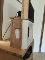
The waveguide is around 3.5cm deep.
Distance from edge of the speaker to port is 13 cm.
Box is 30 by 24 by 14. Inside it is 8.
I think the waveguide controls directivity in the upper frequency.
Crossover is at 400 and 1400hz. Then I have a BMS 5530 with audiohorn x25 (astonishing)
Distance from edge of the speaker to port is 13 cm.
Box is 30 by 24 by 14. Inside it is 8.
I think the waveguide controls directivity in the upper frequency.
Crossover is at 400 and 1400hz. Then I have a BMS 5530 with audiohorn x25 (astonishing)
I predict a 520 hz limit. Proove me wrong! ( i'm (friendly) challenging you 😉 ).
Ideally you would have the directivity to go up to which freq?
1400hz? 6cm max distance from driver to port, you'll have to be creative to include them into the waveguide. I think it can be done, afterall it would not be very different than a MEH... 😏
Or forget about waveguide for this driver?
Edit: bsc should be centered around 383hz from your box dimension. I wonder if the waveguide is needed? The box by itself will take the lead from circa 750hz.
Intriguing waveguide ( x25). Looks a lot like the Jbl or the profile Marcel and friends produce thanks to Ath4. You already listened to it?
Last edited:

The X-Shape are developed in house in AudioHorn, there is a lot of variation/way to do it, even in JBL actual line up, including JBL Synthesis, if you look closely there is 3 or 4 versions cohabiting and if you look carefully the horn doesn't exhibit the same profile as Ath4 and is not related to Marcel (that do a great job also of course).
Pro simulation are done in FEA, not BEM (akabac and co) and FEA require clean geometric model and super computer, it not works with mesh.
The first test with X25 cut at 1250hz with 8" show a cancellation that allow to cut and control until 170hz (200hz on some other 8"), a lot bellow the 520hz limit if you talking about the limit of a cardioide with a 8".
As wave-front become omnidirectionnal at 200hz, so there is a full cancellation starting at this point.
Everything is here : https://forum.soundpixelab.com/viewtopic.php?t=86
Even if it still in development with a different way to do cardioide (that is not on the topic)
Yes I am listening to the x25 with the BMS 5530, after spending the summer sending all my compression drivers to Nicolas who kindly measured it on his x33 horn.I predict a 520 hz limit. Proove me wrong! ( i'm (friendly) challenging you 😉 ).
Ideally you would have the directivity to go up to which freq?
1400hz? 6cm max distance from driver to port, you'll have to be creative to include them into the waveguide. I think it can be done, afterall it would not be very different than a MEH... 😏
Or forget about waveguide for this driver?
Edit: bsc should be centered around 383hz from your box dimension. I wonder if the waveguide is needed? The box by itself will take the lead from circa 750hz.
Intriguing waveguide ( x25). Looks a lot like the Jbl or the profile Marcel and friends produce thanks to Ath4. You already listened to it?
I sold everything (faital hf108r, hf10ak, BMS 4552) and bought a BMS 5530nd.
I had the chance to test the hf108r on x25 before I sold it and it was great improvement over sth100.
I will write a recap on the best CD topic soon. This horns are really worh a try.
The first test with X25 cut at 1250hz with 8" show a cancellation that allow to cut and control until 170hz (200hz on some other 8"), a lot bellow the 520hz limit if you talking about the limit of a cardioide with a 8".
As wave-front become omnidirectionnal at 200hz, so there is a full cancellation starting at this point.
The limit i'm talking about is linked to the way it's done in the D&D 8c, which seems to be the theme of this thread and the way USA-Satriani implemented.
Following this way of doing a cardioid and test/prototype i've done, i can predict what USA Satriani implemented will be limited to 520hz as upper limit for the cardioid behavior - from the ports- from the dimension he gave and i answered that if he want control up to1400hz then driver/port distance should be 6cm. From this it is easy to determine some relationship to define driver/port distance related to an upper frequency limit ( and if you can't find it this way read this thread it had been given in a message 😉 ).
There is other things in D&D approach ( it's all in the patent and a bit of reverse engineering/study of 8c, plus post in this thread) as the fact the box dimension play a role ( the width as it define BSC which play a role if you want to extend the effective range of directivity management), the depth of the chamber ( it's in the patent) and the nature of absorbent used. As implemented in the 8c the lower limit seems to be sub 100hz as this is where they cross to low way. From kimmo experiment ( and commercial products like Gethain's or Genelec) it can be pushed (way) lower but with other compromise/technique used ( passive or active).
Where i find D&D approach interesting ( and as Fluid pointed in a previous post in this thread) it's that Martinj used multiple things together to expand the range on which cardioid behavior happen ( circa 100hz up to 1,2khz which is 3,5 octave) and most of them are passive. I personnaly find it to be a 'tour de force'.
There is very probably other way to implement cardioid but this is not what i'm talking about, i focused on Martinj and Kimmo's ways (which tryed a lot of passive approach too). 😉
I will take a look at linked thread as i'm always interested and curious about way of doing things and because of Tmuikku and Fluid and Vinneeth and Marcel and...( blame on you! Lol) it's been a year i experiment with cardioid. And as it is in my native language it will change ( and i've seen things i enjoyed in some exchange from the eyeballing i've already done! 😉 )
@NicoB, you are part of Soundpixelab that's it? Your waveguide looks like fine products, clever in the design and approach to develop it. Congrats. You should open a thread about it, your design goal and such things, it will interest people for sure. And open for interesting discussions/chat👍
And maybe another one about your way of designing cardio if it's different than the one presented here! The more options... the more bothering! Lol. I'm kidding of course. It's always fine to have different approach.
Last edited:
Yes, I understood from the knowledge from this topic that port shall be as close as possible to the front baffle..but my front baffle is a waveguide so I can't go closer...
I will do that test from behind, it is clever.
Not nescessarely the closest. It depend up to which freqency you want cardioid control (from the ports).
Waveguide/horn in cardio config have been presented by Kimmo as being the one which 'kick' the most ( i associate this with an increase in efficiency and dynamic impact). It can be worth pursuing... or not. Depend of your goal/overall design/ compromise you are ok to make, etc,etc,...
Anyway you prototype so you'll find by yourself what is important for you. It's all what matter imho.👍
You are welcome 😀because of Tmuikku and Fluid and Vinneeth and Marcel and...( blame on you! Lol)
Hello,
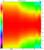
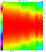
here are the first results from my trial with PHL 1140 in a box with a waveguide and some cardoid ports.
The box is small with melamine sponges inside and some felt behind the driver.
I made a polar with the holes blocked and one with the melamine behind the ports.
We can see a carioid effect but also that some medium around 1khz is obiously escaping from the carioid box !
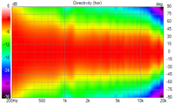
Then I have the final polar with my AudioHorn X-shape X25 horn which is a 90 degtree CD horn. Measurements are of course approximate but this gives a pretty good idea.
here are the first results from my trial with PHL 1140 in a box with a waveguide and some cardoid ports.
The box is small with melamine sponges inside and some felt behind the driver.
I made a polar with the holes blocked and one with the melamine behind the ports.
We can see a carioid effect but also that some medium around 1khz is obiously escaping from the carioid box !
Then I have the final polar with my AudioHorn X-shape X25 horn which is a 90 degtree CD horn. Measurements are of course approximate but this gives a pretty good idea.
Attachments
Last edited:
Results are not bad at all!
Bsc is right where it should circa 750hz, yes you have that 1khz bump in cardio, but it seems to be present in the x25 polar plot too.
How steep are your filters? Maybe there is a cumulative effect? I think the bump in cardio could be related to the port distance too, at least i have observed that in some of my experiments ( and it's equal to half wavelength of port/membrane distance).
I use LR48 filters.
But I think the phl cardio polar was done without filter and with rew doing 300-3000hz sweeps.
As I said I think my ports could be better if longer and thinner ...
I started reading a manta topic and I think they explain why they choose this kind of shape, to avoid medium leaking out of the box and still have an effect in the lows
https://forums.audioholics.com/foru...oid-active-speaker-development-thread.125195/
Please read 😁
Attachments
You might be right, i have not experimented with this so can't comment.
Sd of ports are which ratio of membrane area ( sd)?
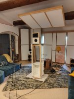
In the x25 round graph there is the same 1khz aberration as with the cardio box. I wonder if it could'nt be linked to your measurement set up as it seems there is a plate on which is mounted the loudspeaker, could be a reflection no?
I read the Siegberg thread on ASR but... i really don't like the overall mood at ASR. Thank you pointing to another one, i hope he will be less reluctant to post measurements there!
Sd of ports are which ratio of membrane area ( sd)?
In the x25 round graph there is the same 1khz aberration as with the cardio box. I wonder if it could'nt be linked to your measurement set up as it seems there is a plate on which is mounted the loudspeaker, could be a reflection no?
I read the Siegberg thread on ASR but... i really don't like the overall mood at ASR. Thank you pointing to another one, i hope he will be less reluctant to post measurements there!
Last edited:
Ok. You could try to make them bigger overall, at 1/1 in next proto, with multiple ports!
@NicoB , you should start a thread in here about your designs. They looks really interestings.
I see a whole lot of new generation of EU based econowave design that could quickly grow with such waveguides!
@NicoB , you should start a thread in here about your designs. They looks really interestings.
I see a whole lot of new generation of EU based econowave design that could quickly grow with such waveguides!
I started reading a manta topic and I think they explain why they choose this kind of shape, to avoid medium leaking out of the box and still have an effect in the lows
https://forums.audioholics.com/foru...oid-active-speaker-development-thread.125195/
Please read 😁
Very interesting thread and with much better mood than the one in ASR!
It's interesting, i arrived to same conclusion about some things as in the Manta but through different path. It's great to see confirmed i'm on right track.
Damn... i'll have to build another proto box to try multiple thinner ports too... i hate you guys. 🙂
Here is a quote from that audioholics thread for the manta
"Firstly, the ports on the front and the ports on the side have different purposes. The ports in the front baffle is as you say an attempt to "trick" the coax into seeing a more narrow baffle, to get a more even off-axis response. "
I've been simulating cardioid coax design in ABEC. My sims have a single aperture on each side 50mm wide by the height of the 8" driver. The sims tell me that if I can fine tune the amount of absorption, the design will work quite well. The methodology is the same as Kimmo suggest for Vituix except that Vituix diffraction models are replaced by ABEC generated polars created separately for the front and rear of the driver.
One thing I have yet to do is replace that single aperture per side by a set of narrow slits. Somewhere in the ABEC help is the suggestion, that parallel slits form an acoustic resistance. (search AcouResistance and "Ra=" in the help file) I found the math required to characterize them obscure but not totally opaque and am hoping I can find a solution without too much trial and error. A cardioid design methodology that doesn't require cut and try except in simulation would be awesome.
I've got similar issues too, around baffle width wavelength. It's likely due to wavelength being short enough output from the ports and front do not match in level and directivity. One could use wide edge rounded baffle to make the directivity happen, and then try and reduce output on the back, or something like this. Try and figure out which one makes the radiation, and why the other doesn't cancel it. The cancellation is both ways, either front or back sound dominates frequency response if the other has less amplitude, or wrong phase relationship. It's impossible to match radiation of sideport(s) and driver to all directions on short wavelength, simply because they are not coincident, and at some frequency these problems start. If one imagines just a hole, it would have it's own baffle diffraction, which is different than that of the driver, because frequency response is different, source size is different, baffle size is different, location on the baffle is different, and it's different direction than the front baffle. Diffraction backwave just makes sound to various different directions than what diffraction on the front does. One could make the box very deep, and try to match the front corner of the port and driver, and things like these, trying to match sound propagating to various directions, from both the front and the apertures. And this is just simplified thinking about what happens there acoustically.
The pattern, or any frequency response stuff, is simply from interference: two (or more) sounds having such phase relationship toward some direction they cancel out, and the closer they are in amplitude and being 180deg out of phase, the more perfect the cancellation to that angle at that frequency is. So, if there is some extra sound to some direction, it's "just matter of" figuring out which one it is, front or back sound that dominates, and why it is there and why the other one is missing, or why they have wrong phase relationship, why there is amplitude difference. Quickly one notices that the fact that these are not coincident would make it happen at some (high) frequency. There likely is some very common pattern here, haven't figured it out yet as been thinking other stuff, for few years 😀
The pattern, or any frequency response stuff, is simply from interference: two (or more) sounds having such phase relationship toward some direction they cancel out, and the closer they are in amplitude and being 180deg out of phase, the more perfect the cancellation to that angle at that frequency is. So, if there is some extra sound to some direction, it's "just matter of" figuring out which one it is, front or back sound that dominates, and why it is there and why the other one is missing, or why they have wrong phase relationship, why there is amplitude difference. Quickly one notices that the fact that these are not coincident would make it happen at some (high) frequency. There likely is some very common pattern here, haven't figured it out yet as been thinking other stuff, for few years 😀
I don't think of it so much as the baffle width frequency as the frequency where the direct sound is widening/transitioning to omni. You've to match widening of directivity of the front radiation with that of the rear. With a single aperture you get what you get. You have to choose between optimizing the rejection at the low end of the range where the front is omni or higher up where its pattern width is changing. But because of this effect, you get a gradual change of directivity, which is a good thing.
With an active cardioid, you have more options, you can shape the phase and magnitude with frequency. You can do more than try various thicknesses of various kinds of absorbers. I'm sure Kii has mastered that trick; I'm starting to get a feel for it.
The manta has a trapezoidal array of slits. Why so, I wonder. Perhaps it is shaping the side radiation directivity intentionally.
- Home
- Loudspeakers
- Multi-Way
- Resistive port cardioid active speaker insipired by D&D 8C