Here is a slightly bigger class A amp and also only used a little blue thing. 🤣 🤣 🤣 🤣 Now this one did not get hot or need fans.


Actually that heat sink was a stupid idea, it was what one would call an absolute overkill. Fans are far cheaper that aluminium. but I had it and no idea what to do with it. It also kept an NC machine occupied for a week-end. There was no reason to make it it was just that I could.
💪Here is a slightly bigger class A amp and also only used a little blue thing. 🤣 🤣 🤣 🤣 Now this one did not get hot or need fans.
View attachment 1354330
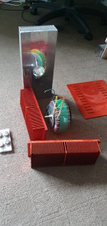
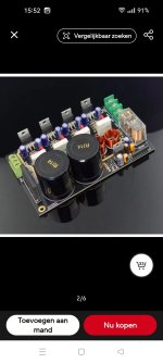
1st photo, hardware for new 1996 version, 5kg heatsinks and 5kg 450va mains TX. Will have fans too.
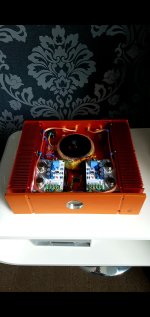
2nd picture my original Chinese JLH1969 so I know about heat, too hot to touch for more than a few seconds, worked great for a year then cooked itself, starting popping. Lessons learned for my new 1996 version (with little blue things)
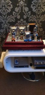
3rd picture, again I know about heat, KT88SE. My Benchmark amp took 6 months to build.
2nd picture my original Chinese JLH1969 so I know about heat, too hot to touch for more than a few seconds, worked great for a year then cooked itself, starting popping. Lessons learned for my new 1996 version (with little blue things)
3rd picture, again I know about heat, KT88SE. My Benchmark amp took 6 months to build.
Attachments
Got the case and assembled the amp for the first try:

I had to put captone on the aluminum angles because transistors were too close to the edge.
First channel worked almost as-is, only had to adjust DC offset on the first transistor. Iq is set to ~0.5A but goes almost up to 1A after 1 hr. Perhaps I need to lower it a bit.
Second channel was a bit more tricky, burned 2 AL100's in the process. There is still something wrong with it, and it looks like second transistor is out of it operating point after the amp heats up. Will continue in next weekends.
And I need to come up with some extender for the power switch 🙂
Attachments
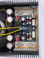
Beautiful!!! 😍😍😍😍 Love it. Like your input combiner to three core RCA cable, that is a first for me. Only guess id that there was short in transistor can and heat sink, even a cracked washer. Cant spot anything wrong on the board. Maybe a burr on the heat sink cutting into the transistor case. I would route the transformer wiring so all AC is on the left. Else good job!
Last edited:
AL100 is a 30 W germanium transistor, I know the sound WILL be different between germanium and silicon. Besides, I don't know if these are fakes as Germanium transistors are very hard to find. MJ15003 is a 140V 20 Amp transistor, a little overkill for running at 2 Amp and 27V, no? Also quite expensive and will get just as hot, so why such a big transistor, 2N3055 is cheap and abundant as well and do the exact same job.
It's Class-A, so bigger is always better for reliability. On the other hand, a good number of people thinks MJ15003 sounds much better than 2N3055 in JLH69. If you check the price of 2N3055 at RS COMPONENTS, there isn't much difference between the two.
Edit- If you think AL100 is ok for JLH just because it's rare & germanium then Good luck to you.
Regards
Edit- If you think AL100 is ok for JLH just because it's rare & germanium then Good luck to you.
Regards
Last edited:
Hello everyone, I adjusted the tuning of my speaker ducts! Now they are well balanced. Here is the video with the tests and adjustments.
Equipment:
2x JLH 1969 Amplifiers - Class A - monoblock (7W rms per channel)
3-way speaker system.
Tweeter, woofer and subwoofer.
Equipment:
2x JLH 1969 Amplifiers - Class A - monoblock (7W rms per channel)
3-way speaker system.
Tweeter, woofer and subwoofer.
You have repaired the China JLH meanwhile;-?!2nd picture my original Chinese JLH1969 so I know about heat, too hot to touch for more than a few seconds, worked great for a year then cooked itself, starting popping. Lessons learned for my new 1996 version (with little blue things)
I would simply use other power transistors, TO-247 or even TO-220 - the TO-3 don't sound very good anyway - and use any heat sink. Then it should run fine and sound even better;-)
Received today 🙂
A long wish of mine....
For JLH69 Class-A.

A long wish of mine....
For JLH69 Class-A.
Very good luck with your build and enjoyment of creating something with your hands, burnt fingers, sweat and dedication. I truly hope that everything is to your enjoyment and satisfaction. Listen to it yourself and make up your own mind if you need to follow others advice and perception which probably is different from what you experience anyway.
MJ15003 is basically a high power 2N3055. So i don't expect miracle but slightly better performance. Anyway it'll take time to build my version of JLH because i'm very busy in my complicated life. This is the only thing (hobby) where i find peace. Btw I like to place a new order for more MJ15003 
Regards to All
Regards to All
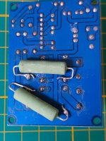
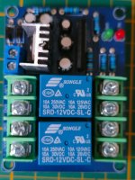
Protection board.@Mooly @NanoFarad ,
I checked the relay and I assume the NC contact isn't available.
View attachment 1346543View attachment 1346544View attachment 1346546
Replaced the relay with the version that has the NC contact pin. Added 10R resistor.
This works great 👍.
But still have some Humm when I connect 12V input of the protection board in parallel with the 12V from an other protection circuit.
(Amplifier has 2 jlh board for tweeter and 1 stereo LM1875 for woofer).
When I feed it with a USB 12v adapter from my laptop, the Humm is gone.
I tried some DC-DC converter on the input of the protection board ( feed in parallel from the other protection board power) but it didn't help.
Any suggestions how to solve this?
Setup is : 2jlh boards with separate protection board
1 lm1875 stereo amp with integrated protection board.
Lm1875 as a dedicated transformer
Jlh had a dedicated transformer with 2 separated secondary windings)
Attachments

Last edited:
The wiring would have to be drawn out to make sense of it but I'm guessing what is happening is that the board is simply cross coupling the grounds and creating a loop.
Try lifting the input grounds to the protection board by adding say 10 ohm series resistors. You can do the same for the ground to the boards from the power supply as well.
Beyond that you need to draw out the wiring so we can make sense of it 🙂
Try lifting the input grounds to the protection board by adding say 10 ohm series resistors. You can do the same for the ground to the boards from the power supply as well.
Beyond that you need to draw out the wiring so we can make sense of it 🙂
@Moody, you mean just add a 10 ohm between the 12v ground connector and the ground lead? The plus side stays untouched.
Any 10ohm will do or need a higher watt version.
I can only do this for the separated protection board. The protecting of the lm1875 is integrated on the board print.
What I did is, from the 12v voltage regulator of the lm1875 I added 2 wires to the 12v supply of the separated protection board.
Any 10ohm will do or need a higher watt version.
I can only do this for the separated protection board. The protecting of the lm1875 is integrated on the board print.
What I did is, from the 12v voltage regulator of the lm1875 I added 2 wires to the 12v supply of the separated protection board.
Attachments
- Home
- Amplifiers
- Solid State
- JLH 10 Watt class A amplifier