You cut the ground leads to the protection board, that is the supply ground and the input ground and add a resistor in series with each lead. A 0.5 watt more than sufficient as it passes only the relay current.

Thanks @Mooly .
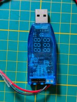
There is some improvement but still not the same level as using the USB 12v dongle.
I also tried 20 ohm but that doesn't change anything compared with 10ohm.
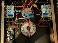
Attached the amplifier.
12v is taken from the LM protection board to feed the jlh separated protection board.
There is a ground lift attached to the negative speaker rail of 1 jlh board.
Input signal ground of the jlh and lm is the same coming from a 3.5 input split into 2 RCAs.
There is continuity between all signal ground from both channels. Input and output.
Also the 12v ground.
There is some improvement but still not the same level as using the USB 12v dongle.
I also tried 20 ohm but that doesn't change anything compared with 10ohm.
Attached the amplifier.
12v is taken from the LM protection board to feed the jlh separated protection board.
There is a ground lift attached to the negative speaker rail of 1 jlh board.
Input signal ground of the jlh and lm is the same coming from a 3.5 input split into 2 RCAs.
There is continuity between all signal ground from both channels. Input and output.
Also the 12v ground.
Attachments
It is difficult to decipher from pictures 🙂
Different idea.... feed the protection board from one supply only in one channel. All I think you are trying to do is get the relay to mute the switch on thump so one supply is all you need. Share the board between the two separate channels with it powered from just one.
Make sure the relay speaker ground terminals for each channel are separate. If you have built the amp as two mono amps then you must end up with NO connection between left and right grounds apart from when you connect it to a preamp or whatever.
Looking back on this. You can not connect voltage rails in parallel if that is what you are doing.But still have some Humm when I connect 12V input of the protection board in parallel with the 12V from an other protection circuit.
Different idea.... feed the protection board from one supply only in one channel. All I think you are trying to do is get the relay to mute the switch on thump so one supply is all you need. Share the board between the two separate channels with it powered from just one.
Make sure the relay speaker ground terminals for each channel are separate. If you have built the amp as two mono amps then you must end up with NO connection between left and right grounds apart from when you connect it to a preamp or whatever.
@Mooly I thought I did my best to make a good picture 🙂
I disconnected the input cables. The ground between the LM1875 and JLH is not connected.
The ground between both JLH boards is still connected.
Each JLH board has it's own secundary winding and powersupply.
The ground is connected on the protection board though.
edit. The relay speaker grounds are connected as well with the ground that feeds the board.
The picture is... fine 🙂 but its very difficult working from images rather than circuit diagrams.
Start at the beginning.
1/ The JLH 69 is AC coupled and so does not need any DC offset protection. All you want is a delay circuit.
2/ If you get the amp working without the board in place and it is hum free then that is your starting point. You mentioned earlier it was OK before fitting the board.
3/ Now connect just the power supply to the board. It should all still be hum free after doing that. So that is just two wires to the board, nothing else.
4/ You should hear the relay click after the delay to prove it works.
5/ Now you look at the relay connections and you make sure they are isolated from the board ground. You might have to cut the print with a knife to achieve that.
6/ You now wire each relay contact set across the speaker output so the output is shorted when the power is off. Do the same for both channels.
That has to work 🙂 You have no speaker grounds in contact with the circuitry on board then. It is all isolated.
I hope I won't disturb this thread, just my experience with jlh69. Can't find mention of transistors I used, it happened that I cannibalised some old pro-logic multichannel receiver and then ran into jlh schematic, said to myself let's try it and I basically used what was on the heatsink, after brief look at transistor parameters. That bird's nest turned out to outclass every other SS amp in the room in terms of clean, detailed and easy to listen sound. Friend tried to make it with NTE transistors, but wasn't that lucky sound wise. There were 2sc5669 outputs, 2sd800 driver and for input I used bc556. Wima/Nichicon/Vishay caps went into it. Sounded really great, I'm waiting for some serious equipment to measure it.
Last edited:
IMO he should try to find two old laptop power supplies and have a half decent kick-off point. I am sure the rubbish dump is full of then.
Excellent output transistors from Sanyo! I have some nice TO-129 Sanyos for JLH driver transistor position, i'll try BD139-16 too. I think own preferences should be based on trial & error (so you need to hve multiple options for components) as well as extensive listening of various genre.
Hi,I hope I won't disturb this thread, just my experience with jlh69. Can't find mention of transistors I used, it happened that I cannibalised some old pro-logic multichannel receiver and then ran into jlh schematic, said to myself let's try it and I basically used what was on the heatsink, after brief look at transistor parameters. That bird's nest turned out to outclass every other SS amp in the room in terms of clean, detailed and easy to listen sound. Friend tried to make it with NTE transistors, but wasn't that lucky sound wise. There were 2sc5669 outputs, 2sd800 driver and for input I used bc556. Wima/Nichicon/Vishay caps went into it. Sounded really great, I'm waiting for some serious equipment to measure it.
What schematic did you use?
Regards
Good question. Fast transistors (compared to original 4Mhz device) can be cause of oscillations. I've c5200 too but not sure how it'll react in JLH. I'll try a small cap in parallel with feedback resistor.
In my opinion, you should try to find the source of oscillation and try to fix it. Just by adding caps to the feedback point is not the answer because the oscillation is still present and just feeding back the problem is not really solving it. Too many designers rely on feed back to solve their problems. Oscillation may be excited in other mechanisms when a signal is applied and maybe go unnoticeable. One should keep feed back other than setting the over all or stage gain to a minimum. Especially non DC feedback because now you are introducing more uncontrolled phase non-linearity. A good PCB layout is essential by trying to avoid parasitic and limped constants to affect your product performance. One of the reasons RF design is often seen as black magic. One should avoid designing a system that far extends the required bandwidth and using components that is faster switching than necessary. If an FT of say 1 MHz is sufficient replacing it with a components of Ft of 100MHz is just looking for trouble from the outset. The components should suit the application.
Last edited:
Hi, I was just following the original article, with notes being taken from eventual revisions. Here you go: https://sound-au.com/tcaas/Hi,
What schematic did you use?
Regards
Had a close look at the board but I cant head or tails of it.The picture is... fine 🙂 but its very difficult working from images rather than circuit diagrams.
Start at the beginning.
1/ The JLH 69 is AC coupled and so does not need any DC offset protection. All you want is a delay circuit.
2/ If you get the amp working without the board in place and it is hum free then that is your starting point. You mentioned earlier it was OK before fitting the board.
3/ Now connect just the power supply to the board. It should all still be hum free after doing that. So that is just two wires to the board, nothing else.
4/ You should hear the relay click after the delay to prove it works.
5/ Now you look at the relay connections and you make sure they are isolated from the board ground. You might have to cut the print with a knife to achieve that.
6/ You now wire each relay contact set across the speaker output so the output is shorted when the power is off. Do the same for both channels.
That has to work 🙂 You have no speaker grounds in contact with the circuitry on board then. It is all isolated.
What I can't see is how the power ground is connected to the speaker ground.
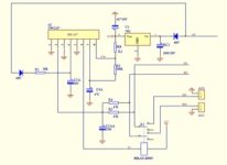
There is no trace on the bottom of the board. I have to desolder components to see how the traces run on the top.
With my multimeter I checked a few.
The attached scheme resemble quiet well the board.
Attachments
Did you work methodically through the 6 points I listed above ? All you are doing is connecting the wires one at a time if you work through those 🙂
The picture you show implies a common speaker ground and your two separate amps should not have that. I agree no separate PSU ground is shown. Maybe as drawn it uses the speaker ground connection/s (well it would have to as drawn).
Begin by wiring just this and nothing else.
Is the amp still hum free like this?????
So the drawing just above should not have any mechanism to introduce hum. Are you 100 % sure that the delay board is 100% isolated from the chassis (and so any ground routes) and that there are just those two wires connected?
All that is doing is adding the small load of the board to the power supply but with no possible route into the signal path.
We might have a couple of different ways of doing this... so this is trail and error...
Is the ground return wire going back to the power supply? Do not connect this ground to any point on the amplifier boards. So the ground wire should go here (circled in red) which is the negative end of the big reservoir caps.
Try connecting just that one wire to begin with and make sure it is hum free.

Where are you connecting the power supply input to your board to. Are you connecting it to the plus rail supplying the JLH or are you feeding it AC direct from from the transformer?
Lets now connect the supply input to the board to the plus rail which would be the plus end of the big caps. That feeds the board around 27 volts DC from memory for a JLH.
Is it still hum free?
Does the relay operate correctly (click in and out) with the correct delay?
--------------------------------------------------------------------------------
The other option we have is to wire the board direct to the AC from the transformer. Lets try the above option first. As long as the relay operates OK it should work. All you want is the delay, there is no point adding the offset sensing because the JLH69 is cap coupled and can not generate an offset across the speaker.
All that is doing is adding the small load of the board to the power supply but with no possible route into the signal path.
We might have a couple of different ways of doing this... so this is trail and error...
Is the ground return wire going back to the power supply? Do not connect this ground to any point on the amplifier boards. So the ground wire should go here (circled in red) which is the negative end of the big reservoir caps.
Try connecting just that one wire to begin with and make sure it is hum free.
Where are you connecting the power supply input to your board to. Are you connecting it to the plus rail supplying the JLH or are you feeding it AC direct from from the transformer?
Lets now connect the supply input to the board to the plus rail which would be the plus end of the big caps. That feeds the board around 27 volts DC from memory for a JLH.
Is it still hum free?
Does the relay operate correctly (click in and out) with the correct delay?
--------------------------------------------------------------------------------
The other option we have is to wire the board direct to the AC from the transformer. Lets try the above option first. As long as the relay operates OK it should work. All you want is the delay, there is no point adding the offset sensing because the JLH69 is cap coupled and can not generate an offset across the speaker.
Have you tried what I set out earlier?
You need to configure it like this as a start. Note all the connections that have been erased.
1. You apply power to the board.
2. You route only the speaker + connection through the board (and so through the relay).
3. The speaker negative feeds bypass the board completely.
You haven't shown the supply to the board but based on what you posted before with the board having a 7812 reg you can connect it to the 27v supply of the JLH. Make sure any caps before the reg are rated at higher than the supply voltage applied.
Try it like that and see where that gets you.
I connected it like you mentioned in the the drawing above.
It is worse then when negative speaker wires goes through the board.
Really strange as I felt it would minimal improve the situation but it didn't.
I tried powering the board directly from the 12v from the lm-board.
Also from the DC input from the jlh.
It is worse then when negative speaker wires goes through the board.
Really strange as I felt it would minimal improve the situation but it didn't.
I tried powering the board directly from the 12v from the lm-board.
Also from the DC input from the jlh.
- Home
- Amplifiers
- Solid State
- JLH 10 Watt class A amplifier