My apologies gentlemen
Usually when designing a PCB I first do all the necessary simulations in LTspice (olg is the most important) and build a prototype.
Only then do I decide that I can share the project.
This time it was different - I don't have an LTspice model for the op-amp Besides, I'm not interested in building this amplifier
This is the first and last time I've uploaded gerber files without fully checking
Maybe someone is ready to make a prototype on veroboard and only then we'll get back to the PCB design?

I am disappointed. I like to close this project.
But as @ZoltanChivay says. If someone would setup this circuit and see what happens then it would be great.
Make a prototype and see if it is stable.
Who will be the first? 🙂
But as @ZoltanChivay says. If someone would setup this circuit and see what happens then it would be great.
Make a prototype and see if it is stable.
Who will be the first? 🙂
Hi @lineup,
don't be discouraged. Your project is very interesting (for me at least!) and may just need some small adjustments to be a great success!
If I find some time I may try to set up a "representative" simulation using a similar op-amp model with open loop graphs.
don't be discouraged. Your project is very interesting (for me at least!) and may just need some small adjustments to be a great success!
If I find some time I may try to set up a "representative" simulation using a similar op-amp model with open loop graphs.
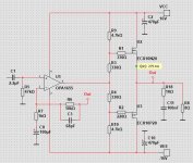
You can add pads on pcb for feedback capacitor. Then simply try both original, and bypass C2 pads with wire and add fb cap. Feed 1k, 10k, 20k into proper load, and watch what happens on osciloscope. Phase margin of 23 degrees is with high likelyhood going to cause osc. Anything below 45 really.
Adding or changing a few paths on the PCB is not a problem.You can add pads on pcb for feedback capacitor
IMO the problem is the untested schematic even though it can be done and we know how
I apologize LineUp but I still remember the discussion about OLG in the Cello amp topic
I remember the "olg for dummies" guide posted by minek123
You have to draw conclusions. OLG it is really a basic and fundamental simulation.
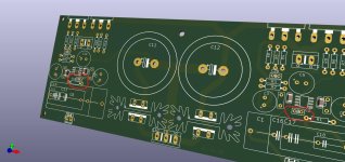
I spent many hours designing the PCB and in the end the circuit is burdened with errors.....
I did not design this PCB for myself but for the DIY community
But I think it is too easy to give up now.
I will make (another) correction to the PCB but this time there will be no Gerbers
I have just ordered op-ams (the only elements missing to make a prototype)
I will build this amp, test it and if EVERYTHING is OK - I will add Gerbers.
Stay tuned
To compensate for the different input capacitance of the N-channel and P-channel lateral mosfets.Why two diferent values for R1 and R2?
I am sorry, but unfortunately I can not make OLG. I do not use LTSpice.Adding or changing a few paths on the PCB is not a problem.
IMO the problem is the untested schematic even though it can be done and we know how
I apologize LineUp but I still remember the discussion about OLG in the Cello amp topic
I remember the "olg for dummies" guide posted by minek123
You have to draw conclusions. OLG it is really a basic and fundamental simulation.
I spent many hours designing the PCB and in the end the circuit is burdened with errors.....
I did not design this PCB for myself but for the DIY community
But I think it is too easy to give up now.
I will make (another) correction to the PCB but this time there will be no Gerbers
I have just ordered op-ams (the only elements missing to make a prototype)
I will build this amp, test it and if EVERYTHING is OK - I will add Gerbers.
Stay tuned
I use Multisim. And I have still to learn how to do this vital test.
Will visit Cello and see what minek123 said.
OpenLoop testing.
I used signal 1kHz 1Vpk.
Magnitude was 0dB at 3.07 MHz.
At 3.07 MHz the Phase is 35 Deg.
I guess this is the called PhaseMargin.
Am I right??
I used signal 1kHz 1Vpk.
Magnitude was 0dB at 3.07 MHz.
At 3.07 MHz the Phase is 35 Deg.
I guess this is the called PhaseMargin.
Am I right??
Usually amp is considered being stable if PM is > 45 degrees.
From my experience, in real world it get worse - with 45 degrees of PM, there is 50% chances that real build will be stable.
I would aim at reaching 60 degrees of PM. With class A amps it's easier.
As Zoltan said - "OLG it is really a basic and fundamental simulation." and no one can claim that "my amp is stable"
if OLG simulation has not been done.
@ZoltanChivay
Yes, that is the page where people teach me OLG.
I have been there and done some reading.
Yes, that is the page where people teach me OLG.
I have been there and done some reading.
You need to retest square waves behavior after this.I tried with 10pF from inverting to opamp out.
PhaseMargin I got to be +49 Deg.
Then I tried with 22pF in same place.
PhaseMargin is now +71 Deg.
Changing compensation values is usually a compromise between stability, and squares... and it's a very repetitive process.
Also, increasing these capacitances ( or adding new ones) makes amp slower.
You can estimate theoretical slew rate based on square waves sim.
- Home
- Amplifiers
- Solid State
- Choctaw - 10 Watt Amplifier, 1 Opamp + 2 MOSFET