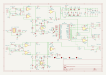
Here is a balanced volume control/ pre-amplifier based around Bruno Putzeys excellent design. In this instance, the original Baxandall volume control section is replaced by the MUSES72323 digital volume controller. The MUSES chip provides two digitally controlled elements
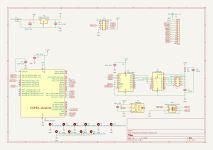
The MUSES 72323 digital interface uses SPI format data and it can easily be controlled from an Arduino, ESP32 or similar.
- firstly a simple resistive ladder network to act as a straightforward attenuator with steps of 0.25dB and can be set to MUTE, then in 0.25dB steps from -117.5dB up to 0dB
- secondly, a resistive network to control the pre-set gain of an externally connected op-amp as a non-inverting amplifier. Gain can be set from 0dB up to +21dB in 3dB steps
The MUSES 72323 digital interface uses SPI format data and it can easily be controlled from an Arduino, ESP32 or similar.
Attachments


Built unit is happily married to a Mooly MOSFET power amp. Resultant system is absolutely quiet and plays music beautifully with no colouration. Adjusting the volume results in smooth transition from level to level with no apparent zipper noise.
Thanks for spotting those two errors in the BOM. Corrected BOM is attachedGeoff, would you please check two lines at BoM?
660-RK73H2ATTDD47R0F
and
596-OPA1656ID
It is relatively easy to adjust, but could be misleading.
Attachments
I've got software code for either Arduino or ESP32 (differences are in one or other library which make use of ESP specific code).Would you happen to have software code to control the MUSES72323 to share?
I'll post them shortly after a bit of shopping (wife nagging she wants food in the house) and also double check the code.
Both sets of code have been used in anger:I've got software code for either Arduino or ESP32 (differences are in one or other library which make use of ESP specific code).
I'll post them shortly after a bit of shopping (wife nagging she wants food in the house) and also double check the code.
Arduino Nano code
The Nano code runs on my old controller board which houses a piggy backed Arduino Nano, a PEC11R/ Alps EC11 rotary encoder, TSOP4836 IR receiver and a ULN2003A darlington array (used to drive separately mounted source select relays). It also feeds i2c data to a 20x40 LCD display.
ESP32 code
The ESP32 code runs on my new controller board housing an ESP32-DevKitC V4 dev board, PEC11R, TSOP4836, and ULN2003A. Apart from the ESP32 in place of the Nano, it also feeds SPI data to an on-board 2.8inch TFT display. Two issues I came across while getting the ESP code working on my new controller board were
- The TFTeSPI library runs the ILI9341 TFT SPI write clock rate as 40MHz. This is 4 times faster than the data sheet and on this set of hardware /ribbon cables is way too fast. The data sheet figure works absolutely fine in this instance.
- The initial hardware/software worked fine on the bench power supply but didn't want to power-on with the pre-amp's power supply . It was happy to work if the reset button on the ESP dev board was then pressed. This was due to the pre-amp power supply had a softer start-up time. (slower than the ESP's dev board's existing reset timing. A 10uF from the ESP32 reset pin to ground cured the problem.
Good question.Very nice project solving a weak spot of the original! But since C35/C36 are included shouldn't there be caps in the other legs as well?
C35/C36 are in the circuit so that any dc offset from the preceding gain stage don't affect the zero-crossing detection of the MUSES chip. The other legs (by which I assume you mean the legs from L+ or R+ to the non-inverting inputs of the op-amp forming programmable gain stages after the MUSES chip) only need coupling capacitors if the following op-amps are bipolar. For FET input op-amps they're not required (see page 7 of the MUSES72323 data sheet).
I haven't tried it but suspect that, as a result of the dc servo element within the Putseys amp, C35/C36 may not actually be needed either.
Hi I think the input caps for MUSES72323 are always needed regardless of JFET or bipolar opamps at the outputs. The caps introduce a phase shift. I am not a professional but I would think the phase shift should be in both legs.
Last edited:
Sorry for the stupid questions but I was intrigued by the original design from the start but noticed the weakness directly and never built it. Despite all the engineering greatness and somewhat shouting article the volume control seemed too risky and likely an error to be expected.
Now you replaced it for an electronic potentiometer that I guess is logarithmic as volume control is normally that. The Putzeys design used a linear potentiometer as it is in the feedback loop of the opamp. Is volume control now not a bit awkward?
Now you replaced it for an electronic potentiometer that I guess is logarithmic as volume control is normally that. The Putzeys design used a linear potentiometer as it is in the feedback loop of the opamp. Is volume control now not a bit awkward?
Last edited:
Nice! 👍 I did the same, and a little more, six years ago with through hole parts. BTW my boards are still available.
The original Putzeys circuit used a linear pot as the feedback element of a gain stage. This circuit is a Baxandall volume controller and actually produces an S shape control law. At very low settings (also at extremely high settings) it accentuates any tiny imbalance in the resistance matching between the two channels so the balance can be a bit variable at very low listening levels.Now you replaced it for an electronic potentiometer that I guess is logarithmic as volume control is normally that. The Putzeys design used a linear potentiometer as it is in the feedback loop of the opamp. Is volume control now not a bit awkward?
This current design, using the MUSES72323, for each step of level adjustment a precise 0.25dB increase or decrease on output is achieved. I haven't bothered on my implementation of the control software but the left and right channels can also be separately adjusted to provide a balance function if you so wanted.
Yes but the question was what a logarithmic volume control will create where a linear one is supposed to be.
The design originally needed a variable linear resistance to avoid the drawbacks of logarithmic potentiometers AFAIK. It was more a gain control potentiometer.
The design originally needed a variable linear resistance to avoid the drawbacks of logarithmic potentiometers AFAIK. It was more a gain control potentiometer.
Thanks Alex. Your boards offer a selection of different approaches to the volume control and include the original linear dual potentiometer plus different varieties of digital volume chips. They do a nice job too and cater for those who shy away from SMD construction. Your MUSES offering is the earlier 72320 chip which works similarly to the 72323 but for 0.5dB steps.Nice! 👍 I did the same, and a little more, six years ago with through hole parts. BTW my boards are still available.
You misunderstand the original circuit. I suggest you read the original Putzeys article.Yes but the question was what a logarithmic volume control will create where a linear one is supposed to be.
The design originally needed a variable linear resistance to avoid the drawbacks of logarithmic potentiometers AFAIK. It was more a gain control potentiometer.
This 72323 implementation achieves what Bruno Putzeys was aiming for with his original Baxandall volume control.
To quote from the original article:The design originally needed a variable linear resistance to avoid the drawbacks of logarithmic potentiometers AFAIK.
As most experimenters will have noticed, potentiometers leave wildly varying and occasionally unpredictable footprints on the sound. Postmodern etiquette then requires that one congratulates oneself on having heard something that doubtlessly the objectivist clique will never have noticed and will most certainly deny, so the new observation is set aside for wonderment and mysticism and, crucially, exploitation by manufacturers of very expensive parts. I must disappoint the postmodern set here. The problem is perfectly well known and wellunderstood if not by too many people. There are two elements at play. The resistive track is rarely linear. On top of that the non-linearity is dependent on the current density in the track. In logarithmic pots the divider ratio becomes non-linear. Also the wiper contact is a source of distortion
Hi geoffw1!Both sets of code have been used in anger:
Arduino Nano code
The Nano code runs on my old controller board which houses a piggy backed Arduino Nano, a PEC11R/ Alps EC11 rotary encoder, TSOP4836 IR receiver and a ULN2003A darlington array (used to drive separately mounted source select relays). It also feeds i2c data to a 20x40 LCD display.
ESP32 code
The ESP32 code runs on my new controller board housing an ESP32-DevKitC V4 dev board, PEC11R, TSOP4836, and ULN2003A. Apart from the ESP32 in place of the Nano, it also feeds SPI data to an on-board 2.8inch TFT display. Two issues I came across while getting the ESP code working on my new controller board were
In the coding, my remote control uses RC5 protocol as this is the coding used by my existing commercial sources that feed the pre-amp. It's straightforward to substitute other coding. Just google for whatever you need (Apple, NEC, whatever).
- The TFTeSPI library runs the ILI9341 TFT SPI write clock rate as 40MHz. This is 4 times faster than the data sheet and on this set of hardware /ribbon cables is way too fast. The data sheet figure works absolutely fine in this instance.
- The initial hardware/software worked fine on the bench power supply but didn't want to power-on with the pre-amp's power supply . It was happy to work if the reset button on the ESP dev board was then pressed. This was due to the pre-amp power supply had a softer start-up time. (slower than the ESP's dev board's existing reset timing. A 10uF from the ESP32 reset pin to ground cured the problem.
Could you please tell me which pins of the ESP32 you connected the rotary encoder (A:33, B:32, SW:12?), IR receiver (27?), ULN2003A and SPI (display+muses) to? Is it possible to change the volume control steps to 1dB steps?
Thank you! Dee
Encoder:Could you please tell me which pins of the ESP32 you connected the rotary encoder (A:33, B:32, SW:12?), IR receiver (27?), ULN2003A and SPI (display+muses) to? Is it possible to change the volume control steps to 1dB steps?
IR Receiver:// define encoder pins
const uint8_t DI_ENCODER_A = 33;
const uint8_t DI_ENCODER_B = 32;
const int8_t DI_ENCODER_SW = 12;
// Rotary construct
RotaryEncoder rotaryEncoder(DI_ENCODER_A, DI_ENCODER_B, DI_ENCODER_SW);
MCP23S08:// define IR input
unsigned int IR_PIN = 27;
// RC5 construct
RC5 rc5(IR_PIN);
And to make sense of all this:// 23S08 Construct
MCP23S08 MCP(10); // HW SPI address 0x00, CS GPIO10
Attachments
Yes, it is but I think you'll find that that's quite a jump on perceived volume in practice.Is it possible to change the volume control steps to 1dB steps?
Google is your friend - have a search for Arduino rotary encoder libraries that have incorporated variable rates of change dependent on how long you are turning the encoder.
- Home
- Source & Line
- Analog Line Level
- Putzeys Balanced Preamplifier with MUSES72323 Volume