The disadvantage of additional or complex psus, e.g. active ones, is that their components modulate the sound audibly. All components involved modulate the sound audibly. The choice of components is also essential here, the maximum current on paper does not have to be, and will not be, the best solution in terms of sound: power, speed, cleanness.
A "Darlington transistor" tends to leave out a lot of details, sounds somewhat darker, has fewer colors.
A "Darlington transistor" tends to leave out a lot of details, sounds somewhat darker, has fewer colors.
Incidentally, our ABx Switch Box proves to be a very valuable tool and good investment.
It just allows you to verify a lot of claims about passive and active devices, power supplies, ...... with a direct comparison.
One does not have to do it the complex way as we did.
A pair of 8A DPDT gold plated relays and a remote switch is all you need, for the occasional use.
😊
Patrick
It just allows you to verify a lot of claims about passive and active devices, power supplies, ...... with a direct comparison.
One does not have to do it the complex way as we did.
A pair of 8A DPDT gold plated relays and a remote switch is all you need, for the occasional use.
😊
Patrick

Maybe we no longer need masters like Nelson, John, Charles, Dimitri, Bob, .....
Only some AI software which will generate one Holly circuit to best all others.
What a future to look forward to.
😊
Patrick
Only some AI software which will generate one Holly circuit to best all others.
What a future to look forward to.
😊
Patrick
Long ago, a very good friend of mine came to me and said "My music composition software is nearly complete".
I said "You're only half way there: you still need to write a music critic software and turn them loose against each other, and leave us out of this."
I said "You're only half way there: you still need to write a music critic software and turn them loose against each other, and leave us out of this."
Don't forget Jean Hiraga himself, he is still alive and kicking!Maybe we no longer need masters like Nelson, John, Charles, Dimitri, Bob, .....
@grunf are you back from Alps? 😇 I am looking for your schematics for the positive and negative series reg. 🙏I'm coming back from vacation next week, I'm going to the Alps tomorrow to rest from the sun and the sea (and crowds) and then I'll post the scheme for the positive and negative series reg 😉 .No worries, you will also have green LEDs.
The Toshiba 170/74 have arrived. Because nobody wanted to, or could, assess their sound:
I have heard the SK170 compared to others, NPN, MosFet, Fet in TO-92. The sound is very elaborate: Its material is like from another time. We hear the material here also: the higher strength and "mass stiffness relation". This sound can be reproduced with current "thinner" MosFets and Fets per mod. But it is certainly one of the best and therefore does not belong in a Le Monstre or other complementary transes pp concepts. And certainly not with the mentioned power and driver transistors. That's pearls to swine!
I have heard the SK170 compared to others, NPN, MosFet, Fet in TO-92. The sound is very elaborate: Its material is like from another time. We hear the material here also: the higher strength and "mass stiffness relation". This sound can be reproduced with current "thinner" MosFets and Fets per mod. But it is certainly one of the best and therefore does not belong in a Le Monstre or other complementary transes pp concepts. And certainly not with the mentioned power and driver transistors. That's pearls to swine!
Cumbb, I am trying to figure what you mean with above statement, are they nicer sounding than for instance 2SK1058 and 2SJ162
I can order these two mentioned and will tell you how they sound in comparison to other TO-247 or even TO-3P;-)
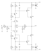
For beginners a schematic with the new components that went along with the description would have been nice. Not everybody has your level of expertise.The schematics is the original Hiraga as in the first picture of the pdf.
All the details of the other versions are fully described in the article.
Anyone can easily follow and build their own.
You have a wide selection of PCBs on the internet to choose from.
And there are also offers for GR grade JFETs as well as ALL BJTs.
I have also described how to use BL grade JFETs.
You need nothing from us.
Cheers,
Patrick
Excellent remark Tailgunner.
It was off to a very good start and it would be a shame to stop there. We are well on a Do It Yourself forum, aren't we! So...
It was off to a very good start and it would be a shame to stop there. We are well on a Do It Yourself forum, aren't we! So...
We are well on a Do It Yourself forum, aren't we! So...
... do it yourself. 😉
Download the image of the original, and modify with photo editor.
Like everyone else.
https://andiha.no/audio/projects/AlaHiragafig/a.png
Cheers,
Patrick
Last edited:
But where is the CCS in the original diagram (https://andiha.no/audio/projects/AlaHiragafig/a.png)?
Have you published any diagram including the CCS? Your answer is not satisfactory; all that for that...
This topic loses all credibility and suggests that the goal was to sell kits. I repeat myself but, in my opinion, this has no place in a Do It Yourself forum since someone who does not have the necessary knowledge cannot produce anything himself with this kind of behavior.
Apparently you have to pay to do...
This is very disappointing!
👎
Fortunately there is a lot on this forum with indepth analysis and description of possible amplifiers to build for the novice so we don't have to listen to a knowitall.
To imply that someone "should" provide you information and work for free is absolutely absurd, particularly after that person has shared a great deal. A great number of people can build this project without a kit and without paying any money. The fact that you cannot is only your personal problem.But where is the CCS in the original diagram (https://andiha.no/audio/projects/AlaHiragafig/a.png)?
Have you published any diagram including the CCS? Your answer is not satisfactory; all that for that...
This topic loses all credibility and suggests that the goal was to sell kits. I repeat myself but, in my opinion, this has no place in a Do It Yourself forum since someone who does not have the necessary knowledge cannot produce anything himself with this kind of behavior.
Apparently you have to pay to do...
This is very disappointing!
👎
Patrick has put out a great number of incredible designs for us to try. If you do not have the skills to build this particular project, a few options could be:
Learn
Build another project.
One CCS (or simpler: A resistor) is connected between TP1 and TP2, and the other between TP3 and TP4.
Exactly, It has been explained before. 🙂
In detail, in the pdf in post #1.
Patrick
Last edited:
- Home
- Amplifiers
- Solid State
- Hiraga Le Monstre 2024