I have revisited my ELD amp designed about 20 years ago that was inspired by a previous thread in the last week or so. Its distortion I cannot measure on anything available to me, only by simulation.
According to MicroCAP-12 simulator there is an improvement from the original that uses no boutique components and are run-of-the-mill semi-conductors. However, all transistors, resistors and caps were closely now matched on the equipment I have available.
Now the distortion profile is not monotonic as Hugh would prefer and I cannot hear any difference in the un-modified channel compared to the modified channel.
Since I have gone through the trouble doing one channel, I may as well do the other and be done with it. I am not publishing it here to receive any praise of any kind, I would just like to share it with anyone that may be interested to build it. All Gerber files are available should you want it.
I cannot really tell what it sounds like, probably nothing, it reproduces music, that is about all. What I have done was to connect the input to one channel of a scope and the output to the other channel and played both music, sine and square wave through the amp. I performed an A-B comparison on the scope and I see nothing but a straight line. I tried running a square wave through MicroCAP-12 but it just hangs on step size too small. All I could do was run a battery switching on then reverse voltage and saw only a slight delay in the transient response and guess that is probably the best answer I will get.
I don't even know whether I am satisfied with these small mods, mainly resistor changes, I am now swapping components to the remaining channel and be done with it until I itch again.
I would be keen to have some comments for improvements because it is not only distortion that is of significance, but hey everyone are hooked on THD. The THD was simulated at full 100 watt, below the onset of clipping.

Nope, the text link does mot show. it is connected else you would have infinite gain. Sorry I did not see the text was in different colour.In the diagram from post 1, isn't there a missing connection at resistor R41 ?🤔
Yes absolutely right.It looks like a label is missing: "output", that is the feedback network.
+-55V 100 watt (That text labels did not show either sorry.What is the voltage supply and the max output watt?
I posted directly from microcap, I think that is why the text label does not show. My stupidity not checking. I did print screen and posted.
The simulation shows that the amp has a pretty good chance of measuring well. Did you ever measure it?
If the circuit is as good as the simulation, then the PCB layout will likely determine the performance of the amp.
Tom
If the circuit is as good as the simulation, then the PCB layout will likely determine the performance of the amp.
Tom
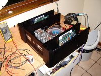
Sorry folks, my bad. I had to use BD140at Q15, I ran out of small signal transistors when I updated the boards, I show what I had on hand.
The metal work was about 10x the price of the electronics. I Had the facia machined from 20mm Aluminium unfortunately, the machinist sandblasted it instead of glass bead blast so its surface finish did not turn out as I wanted. I think I would have done a better job with fine grit water paper.
No it adjusts the output off-set to zero. It defeats nothing, think of the unimaginable low distortion it is: 0.000002% show me something on earth or heaven that can achieve this with component6s from your junk box. Now if I had some decent stuff,, we could think of two orders lower IMKD and THD, in fact it is already nothing, so it will be nothing/20\]
C2 has nothing to do with degeneration and has everything to do to keep the emitters at the same ac voltage while the offset can be adjusted by the DC voltage. Pretty clever, yes?
C2 has nothing to do with degeneration and has everything to do to keep the emitters at the same ac voltage while the offset can be adjusted by the DC voltage. Pretty clever, yes?
not really.Pretty clever, yes?
There are good reasons for emitter degradation resistors besides THD 0.000000000000000
The amp is biased to 1,6 watt class A. I am curios no one ask why there is no source or drain resistors.
Now what would you suggest the are for and we settle that. make them equal and the output offset goes bananas. Yes they are for DC balancing of the tail, that is called degeneration, but we do not want absolute balance and that is why people add a potentiomenter here so they can adjust the dc offset. But as soon as you start messing with the DC at the emitter you change the hFe (dc gain), but we are not interested in the DC component just the AC component to be identical at both emitters for the signal while the DC offset remains independent of the signalnot really.
There are good reasons for emitter degradation resistors besides THD 0.000000000000000
- Home
- Amplifiers
- Solid State
- Is this amp THD good enough?