Hello, I just ordered replacement caps for the heater circuit. It seems like there is ac ripple on it. I also re-flowed all the solder joints. I have a question about chassis ground and signal ground. Should the be separate?
Yeah I normally ground the "safety" earth ground in one spot and the signal ground to another. But you said you tried a ground lift, so that probably isn't it.
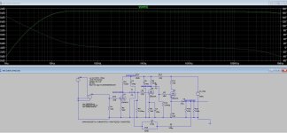
I was curious about this inexpensive phono preamp, so I took the schematic and simulated it in LTspice. There's something I want to show you.
With the parts values as shown, this is the frequency response the simulation predicts (into a 50k ohm load):

The response is a full +1dB at 1kHz compared to at 100Hz and 10kHz. You'll definitely hear that, and it might not sound good with some kinds of music. I wonder if the simulation is close to reality. If it is, this could definitely be improved. So...
I changed R29 from 910k to 750k ohms, and this is what the simulation predicts:

Notice the big difference in the scale (in dB) on the y axis. The frequency response is now within -0.25dB of the output at 1kHz across the audio band.
It's just a simulation, but the difference is pretty big.
With the parts values as shown, this is the frequency response the simulation predicts (into a 50k ohm load):
The response is a full +1dB at 1kHz compared to at 100Hz and 10kHz. You'll definitely hear that, and it might not sound good with some kinds of music. I wonder if the simulation is close to reality. If it is, this could definitely be improved. So...
I changed R29 from 910k to 750k ohms, and this is what the simulation predicts:
Notice the big difference in the scale (in dB) on the y axis. The frequency response is now within -0.25dB of the output at 1kHz across the audio band.
It's just a simulation, but the difference is pretty big.
Interesting as the EAR834 uses a 750k in that position and I wondered if that needed to be changed but I didn't want to spend any more time on it. Looks like changing that to 750K might be worth trying.
Check that the heater windings oming from the transformer have a grounded center tap, either a direct wire or a pair of 100R resistors to ground.
Read up on ValveWizard
Read up on ValveWizard
Definitely. All three time constants are wrong with 910k. They're a lot closer with 750k, although these designs that rely on limited gain can never be very accurate at frequencies below 500.5Hz.Interesting as the EAR834 uses a 750k in that position and I wondered if that needed to be changed but I didn't want to spend any more time on it. Looks like changing that to 750K might be worth trying.

I was curious about this inexpensive phono preamp, so I took the schematic and simulated it in LTspice.
[…]
It's just a simulation, but the difference is pretty big.
Interesting! What resistor value would give a 1-2 db bass lift?
1-2 db 1khz attenuation?
Among the other mods suggested by OP, it could also be fun to listening test and tune with a variable R29.
🎺🙂🎸
Nice changes stephe.
Throw away their board imho if you really want to get rid of all hum - which usually comes from some ground loop. Even the DC heater circuit can cause a ground loop if you are not careful.
Here is a simulation using 720k in the RIAA feedback loop. Using higher values ends up in a 1kHz bump. I actually measured the RIAA and it came up quite flat with these values. Note - the second RIAA feedback 110pF capacitor is really critical. If you mount it on a circuit board, consider that the board itself may have a few pF capacitance as well. Higher values for this second RIAA cap reduce frequencies above 1kHz.
I got rid of the 12ax7 cathode follower in my own version. 12ax7 is no good for driving cables, even as a follower. I replaced it with a MOSFET follower circuit with a far lower output impedance and much more drive. I use a 0.47uF instead of 1.0uF coupling capacitor with the MOSFET follower, and can drive LONG cables if I want to without sonic degradation. Also, 1.0uF is a cheaper/easier fix but it can also let in low frequency turntable sounds and resonances...
I also bias it a little differently, use a higher B+ and fully regulated supplies. Zero hum. Even with cheap china/russian 12ax7's.
Attached is the circuit as modified (mostly) but with 720k in the RIAA feedback loop.
Hello, I have a Little Bear T11 and have done several mods that you mentioned in your videos. Overall I am pleased with the outcome however the excessive hum is very distracting. This is a problem that I can’t seem to solve. Any advice?
Throw away their board imho if you really want to get rid of all hum - which usually comes from some ground loop. Even the DC heater circuit can cause a ground loop if you are not careful.
Here is a simulation using 720k in the RIAA feedback loop. Using higher values ends up in a 1kHz bump. I actually measured the RIAA and it came up quite flat with these values. Note - the second RIAA feedback 110pF capacitor is really critical. If you mount it on a circuit board, consider that the board itself may have a few pF capacitance as well. Higher values for this second RIAA cap reduce frequencies above 1kHz.
I got rid of the 12ax7 cathode follower in my own version. 12ax7 is no good for driving cables, even as a follower. I replaced it with a MOSFET follower circuit with a far lower output impedance and much more drive. I use a 0.47uF instead of 1.0uF coupling capacitor with the MOSFET follower, and can drive LONG cables if I want to without sonic degradation. Also, 1.0uF is a cheaper/easier fix but it can also let in low frequency turntable sounds and resonances...
I also bias it a little differently, use a higher B+ and fully regulated supplies. Zero hum. Even with cheap china/russian 12ax7's.
Attached is the circuit as modified (mostly) but with 720k in the RIAA feedback loop.
Attachments
Last edited:
Definitely. All three time constants are wrong with 910k. They're a lot closer with 750k, although these designs that rely on limited gain can never be very accurate at frequencies below 500.5Hz.
True. To get the most accurate values, a measurement using an inverse-RIAA network is needed. Also, in the original schematic the input valve especially runs at a somewhat low plate voltage. This means the user will discover quite different sonic variations when changing that 1st valve with other manufacturer samples, etc. The RIAA correction also relies on the plate resistance of the 12ax7....
But if you solve all the issues (and the really weak 12ax7 cathode follower) the circuit performs exceptionally well.
Ian
It’s not just component values. To get an accurate curve, a parallel resistor is needed, and much more open loop gain. Without that the curve can never be right. It is algebraically impossible for this circuit to deliver accurate RIAA.
Last edited:
Right, I noticed that the first stage 12AX7 runs at very low plate voltage and plate current. That means gm will be low, rp will be high. There's also cathode degenerative feedback, which reduces gain, which reduces Miller effect capacitance (which is a good thing) but PSRR of that first stage will be degraded (a not so good thing). Lots of interesting compromises made in this circuit.
6N2P has lower Cp-g than 12AX7, which means that first stage could be made to have lower input capacitance. That would help it work with less of a resonant bump in the treble from modern MM carts and SUTs. I made a 12AX7 preamp and found it was pretty sensitive to what cartridge was driving it. The Audio Technica MM carts I like don't like being loaded with 300pF or more of parallel C (Ccable plus Cmiller from the 12AX7 input stage).
In the feedback loop, you could put a 680k and a 39k resistor in series to get 719k ohms, which would be about ideal. Reduce the value of the 39k to introduce a midrange scoop around 1kHz.
Re: Open loop gain...
The Marantz 7C had feedback around two gain stages instead of only one (from output of the last cathode follower to the cathode of the input stage 12AX7). This circuit has FB only around the second stage 12AX7. But many people think the EAR 834P is something special. The EAR 834P looks like it has lots of gain as is, like 44dB (simulated), so maybe people like the sound because of the relatively low amount of NFB applied(?). Simulation says THD is quite low, even with all that.
I need another phono stage like I need a hole in my head, but this is making me curious. I don't think I've ever heard an 834P.
I love the sound of mine. I build mine using the black and gold Zhili Audio boards found on ebay. Yeah it does have a bit of bass boost, but IMHO most vinyl sounds better with a big of bass boost. I use short cables and drive high impedance tube amps so the 12AX7 follower is fine, but it will struggle with low impedance amps. It does have a lot of gain, which I don't mind either. I also don't mind if changing the brand/type of tube (mainly the 1st tube) changes the sonic signature a bit, allows for tuning to your taste/system.
Attachments
Those look nice. 🙂
Are the Zhili Audio boards wired so that you absolutely have to use a 12AX7 in the cathode follower position? Or can a different type be substituted there? It looks like 12AT7 would work fine, but the PCBs may be wired up so that the cathode followers are shared sections of a 12AX7. That would be a bummer.
Are the Zhili Audio boards wired so that you absolutely have to use a 12AX7 in the cathode follower position? Or can a different type be substituted there? It looks like 12AT7 would work fine, but the PCBs may be wired up so that the cathode followers are shared sections of a 12AX7. That would be a bummer.
Okay, what happens when a 6n2p is used? There is no center tap heater wiring on that tube.Check that the heater windings oming from the transformer have a grounded center tap, either a direct wire or a pair of 100R resistors to ground.
Read up on ValveWizard
With 6.3V heater supply:
- for 12AX7, pins 4 and 5 are shorted (+6.3VDC goes to that), pin 9 goes to ground. (No shield)
- for 6N2P, pin 4 goes to 6.3V, pin 5 goes to ground, pin 9 is the shield and can go to chassis or 0V signal ground.
Where you see the word 'ground' in the above, that will be at the junction of the voltage divider resistors (at +76V). Make sure the bottom resistor of the voltage divider is fully bypassed by a capacitor.
The internal shield in the 6N2P needs to be connected correctly. If it is connected correctly, it should provide some shielding between triode sections, so perhaps better channel separation (less crosstalk) and maybe a bit lower hum.
--
Last edited:
I'm pretty sure people mod these boards to use a different cathode follower tube just changing some resistors. Honestly, these sound so good built using hand selected quality parts exactly as printed on the boards, I'm kinda afraid to mess with them 🙂 I have experimented with some different parts and settled on Cornell Dubilier 1% mica caps and alum/oil mundorf coupling caps. Then populate with modern production EH7025 tubes.Those look nice. 🙂
Are the Zhili Audio boards wired so that you absolutely have to use a 12AX7 in the cathode follower position? Or can a different type be substituted there? It looks like 12AT7 would work fine, but the PCBs may be wired up so that the cathode followers are shared sections of a 12AX7. That would be a bummer.
I was referring to the windings from the transformer. There must be a reference to Ground in the heater supply, unless it's Elevated, in which case the DC voltage will be applied at the center-tap.Okay, what happens when a 6n2p is used? There is no center tap heater wiring on that tube.
And the shield (Pin 9) is more useful when the tube is used as a composite gain stage, where the cathodes may sit apart by dozens (or hundreds) of volts.
I'm pretty sure people mod these boards to use a different cathode follower tube just changing some resistors.
Check the blue box in the upper right corner, it lists the ideal v3 Cathode resistor for 12A*7 types.
From the LencoHeaven webpage on the 834p
w
- Home
- Amplifiers
- Tubes / Valves
- Mods to "Little Bear" phono-preamp