This happened to me
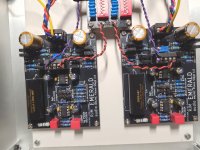
Over the weekend, I powered it up and measured it -- and tested both channels [a full dual mono-channel design] -- one channel was working perfectly, the other saw 0.01 V after the regulator [bad]. Sure enough, in troubleshooting today, I found that I had switched a couple of PNP with NPN transistor, which made the regulator stage "non-functional" -- some additional desoldering/soldering and two BD136 and BD135 transistors, and we got +/- 12.3V to feed the NJP MUSE 3 and OP134 op-amps I use. All good
Over the weekend, I powered it up and measured it -- and tested both channels [a full dual mono-channel design] -- one channel was working perfectly, the other saw 0.01 V after the regulator [bad]. Sure enough, in troubleshooting today, I found that I had switched a couple of PNP with NPN transistor, which made the regulator stage "non-functional" -- some additional desoldering/soldering and two BD136 and BD135 transistors, and we got +/- 12.3V to feed the NJP MUSE 3 and OP134 op-amps I use. All good
I've checked and BD135 and BD136 transistors are in the correct positions and I have also tried re-soldering these but still get the same results.
Would a faulty transistor be a possibility - I must admit I'm a bit of a novice when it comes to troubleshooting
Would a faulty transistor be a possibility - I must admit I'm a bit of a novice when it comes to troubleshooting
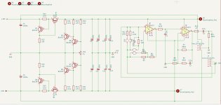
Follow the voltage on the V++ through the regulation circuit towards V+. It should be 18 V or so at V++ and just a tad less at the Q3, emitter then drop to 11 V or so on the Q3 collector then 11 V at the V+ pin.
Clearly it isn't 11 V at the V+ pin, but it is useful to narrow down where the voltage is lost.
Clearly it isn't 11 V at the V+ pin, but it is useful to narrow down where the voltage is lost.
Hello Richard, i use the VSPS with 18V (15V transformer) and it works great - are the 18V für the emerald ok? I have some LT1007 OPAs, are they working well?
Best regards, Thomas
Best regards, Thomas
One of the transistors was installed the wrong way round. Fixed and now workingFollow the voltage on the V++ through the regulation circuit towards V+. It should be 18 V or so at V++ and just a tad less at the Q3, emitter then drop to 11 V or so on the Q3 collector then 11 V at the V+ pin.
Clearly it isn't 11 V at the V+ pin, but it is useful to narrow down where the voltage is lost.
Thanks

Now I have finished the pre-amp. It works great on one channel, on the other it sounds as if the tweeter is defective.
The OPAs are all OK, the jumper also works. I suspect an electrolytic capacitor is defective. If the voltage after the R11 is correct and the OPAs are OK, there it could only a capacitive out of range - is that correct?
The OPAs are all OK, the jumper also works. I suspect an electrolytic capacitor is defective. If the voltage after the R11 is correct and the OPAs are OK, there it could only a capacitive out of range - is that correct?
Do you mean the treble is distorted or simply missing?
If it's the former, I'm not sure, but I suspect a bad solder joint or similar connection issue.
If the latter, I wonder if the resistors in the RIAA filter got mixed up or a wrong value was used, though it's possible that a bad solder joint might have left a critical component open circuit.
If it's the former, I'm not sure, but I suspect a bad solder joint or similar connection issue.
If the latter, I wonder if the resistors in the RIAA filter got mixed up or a wrong value was used, though it's possible that a bad solder joint might have left a critical component open circuit.
Hi...
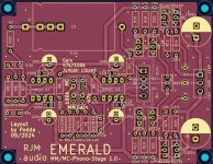
because i wanted to build the emerald phono too, i have made pcb's with kicad. I have a problem in the moment i can't solve. On both boards i can adjust the voltage, but i have no time to run both boards for a longer time, because on one board two transistor pairs become very hot, Q5/Q8 and Q6/Q7. I looked for a mistake, nothing to find in the moment...
On both boards the voltage is following the pot. For the first test i adjusted the pot to 455 ohm on both sides, measured at the board. I am using a 2x 12 Volt transformer and get about -13,65 Volt/+13,65 Volt on the rails. After half a minute the two transistors pairs on the second board have reached about 50 degrees. On the other board the pairs stay cool.
There is only a little change at the input. I can choose between 47 and 100 K. Instead of BD139/B140 i use BD135/136. I have matched the pairs as good as possible. The rest is similar to the original schematic.
Any idea for searching ?
Attachments

@Kleinhorn
If one board is ok and the other faulty, we know it's not the board layout/design.
Q5,6,7,8 is the current sink part of the circuit, but it will only sink as much current as can be supplied by Q1,2,3,4. I'd double check R14 and R15 are really 22 ohms, and check all the resistor values on that part of the circuit, then check all the transistors are the right type (pnp vs npn) and the right orientation.
When you say 13.65 on the rails, this is the regulated output I assume, right? That seems to imply that Q5,6,7,8 are doing their job, it's just they are being fed too much current by Q1,2,3,4. Again, my main point of concern centers on R14 and R15, as these set the bias current of the power supply.
Thank you very much for your fast answer.
Yes the voltage of 13,5 volts is the regulated voltage, measured at the testpoints near to REF. At the output of the diode bridges i got about 10,4x/10,7x volts.
I soldered out Q1-Q4 and measured them....nothing to find, exept a difference of 30 mV Vbe. hFE is equal, 156 hFE.
All resistors have the right value. The transistors have the right orientation.
The problem remains. I ordered more transistors to get pairs with closer Vbe. That will take a few days.
In the meantime i will build one new board. I could not find any mistake by measuring the tracks to the components, but who knows..
Greets
Peter
Attachments

What is the voltage drop across the 22 ohm resistor R14,15? Are they different from the working board?
(should be about 0.5 V)
(should be about 0.5 V)
I cant measure in the moment. I have soldered yesterday evening a new board and im waiting for the delivery of new transistors. As i have done that, i took all resistors out and measured them before putting in on the new board. All have the right value. But if the problem remains, i dont hope so, i will measure the drop voltage over the two resistors. The resistors in the supply area got 22,2 ohm,10k with 9,95 k, 475 ohm got 470 ohm. I dont think that there is a problem. I will try to match new transistors closer. The BD 136/135 remaining in my stock at home are too different to make a test with them.
I will write about my experiance...
Thank you
Peter
I will write about my experiance...
Thank you
Peter
Last edited:
I think i will find the mistake...not the first time something is not working as i should do...in the past i found the fault.
A few transistors are on their way...
Greets
Peter
In the meantime i destroy some other boards....🙂
A few transistors are on their way...
Greets
Peter
In the meantime i destroy some other boards....🙂
Some transistors were delivered and i soldered 4 pairs in. The problem remains. The board on which the transistors keep cool let drop 0,6/0,4 mV at the 22,1 Ohm R14/15 resistors. But on the other board, on which the transistors get hot, i can measure 2,1 mV at each resistor, R14/R15.
If i compare R16/17 on both boards i can meausure 0,89/0,84 Volt, the other board 2,91/2,61 volts.
R20/21 got 12,81/13,10 and on the other board 12,86/13,03 volts. R13/R12 12,87/12,89 and on the other board 12,75/12,87 volts.
The voltage on R18/19 is different too, 0,8/1,5 volts to 2,34/2,37 volts
The voltage is too high on many resistors, but no idea why....
The pot is not adjusted finally, because i will not run the board with hot transistors.
The transistors have the same and right orientation. I could compare with the original layout and mine. Did 4 times ???
The values of the resistors are the same...explicit the 22,1 ohm resistors.
Arghhh....WTF
Nice weekend
Peter
I give it up with my boards. I have ordered original pcb's at JLCPCB, will take a week.
Q1/Q2 are new transistors, don't cant measure something is shorted. I have changed all resistors to new ones, does not matter.
If i compare the original schematic with mine i can see no diiference.
Last try...i solder Q1/Q2 out and put new transistors in....
Thanks for help...
Peter
Q1/Q2 are new transistors, don't cant measure something is shorted. I have changed all resistors to new ones, does not matter.
If i compare the original schematic with mine i can see no diiference.
Last try...i solder Q1/Q2 out and put new transistors in....
Thanks for help...
Peter
The board on which the transistors keep cool let drop 0,6/0,4 mV at the 22,1 Ohm R14/15 resistors. But on the other board, on which the transistors get hot, i can measure 2,1 mV at each resistor, R14/R15.
If i compare R16/17 on both boards i can meausure 0,89/0,84 Volt, the other board 2,91/2,61 volts.
R20/21 got 12,81/13,10 and on the other board 12,86/13,03 volts. R13/R12 12,87/12,89 and on the other board 12,75/12,87 volts.
The voltage on R18/19 is different too, 0,8/1,5 volts to 2,34/2,37 volts
As @kenta16807 notes, I must assume you mean 0.4~0.6 V drop across R14,15 working, 2.1 V (!) on the bad board. It means the current source is supplying about 95 mA on the bad board, compared to about 23 mA for the good one (23 mA is expected and normal). The current sink is receiving all that excess current, and more, as 2.91/2.61 V indicates 132 mA and 118 mA respectively. It's unclear to me how R16 can be passing more current than R14. It should be the other way around as all the supplied current passes through R14 while only the "leftover" current (that is not used by the IC1 or R18 or R20) should be diverted through R16. It's interesting that the output voltages remain correct - after all this, the regulation circuit is still capable of doing its job!
Since you've already replaced almost every part it is possible to replace, I can only imagine that there is a physical fault on the board, either the board itself or as a result of soldering. The bizarre situation re. the measured currents makes me wonder if the output part of the power supply got accidentally bridged to one of the input power rails (V++, V--), essentially feeding current into the output...
As i wrote..i ordered original pcb's. The pcb's are set on production progress and it will take about one week for their delivery. I dont want to waste my and your time any longer.
I will build two new boards, hoping the boards are working. If i get the new pcb's i can compare the tracks and perhaps find a mistake.
It is the first time having such a trouble. Other pcb's i designed are working well...i will see...
Many thanks for your support....
I will report...
Greets
Peter
I will build two new boards, hoping the boards are working. If i get the new pcb's i can compare the tracks and perhaps find a mistake.
It is the first time having such a trouble. Other pcb's i designed are working well...i will see...
Many thanks for your support....
I will report...
Greets
Peter
- Home
- Source & Line
- Analogue Source
- RJM Audio Emerald Phono Stage Help Desk