In the schematic, the first rectifier's negative is connected to ct, and the negative side of those 4 capacitors is connected to B-. not A-.Nope
Rectifier A positive DC side
Rectifier A negative DC side

^ Ah - possibly a misinterpretation on my part.
When I think "rectifier' - I think of a monolithic 4-diode unit. So, I see only one "rectifier" in the schematic.
Clearly I am not an electronics expert. 🙂
When I think "rectifier' - I think of a monolithic 4-diode unit. So, I see only one "rectifier" in the schematic.
Clearly I am not an electronics expert. 🙂
This should say "Rect B-" shouldn't it?
(Looks more closely…) Yes, it probably should as that is where the negative side of the rectifier would connect to the power supply PCB.
So it's labelled logically, not where you should solder the wires onto the boards? It's the B rectifier's negative terminal on the negative side of those caps, the A- terminal is grounded/center tapped, and on the schematic, the negative terminal of the single rectifier version goes to the negative side of the capacitors, not center tap.
I might be too stupid for this, but I swear the negative terminal of the single rectifier version seems like it should go to rect B- on the board.

You are not too stupid at all, you’ve got it completely right.
Transformer CT to CT on PCB
Single rectifier + to RECT A + on PCB
Single rectifier - to RECT B - on PCB
Transformer CT to CT on PCB
Single rectifier + to RECT A + on PCB
Single rectifier - to RECT B - on PCB
Right, hence the confusion, in the drawing the single rectifier version has the - leg of the rectifier labelled "rect A-" and if I put that wire where it says rect A- on the board rather than rect b-, we're gonna have problems heheheSingle rectifier - to RECT B - on PCB
Oh! You’re talking about matching the schematic to the silkscreen on the later revision of the board.
All understood. 😀. Sorry if I caused confusion.
All understood. 😀. Sorry if I caused confusion.
Whatever you hit first;
1/2 your transformer VA in W of bias (total amplifier)
Mosfet 60C and heatsink 50C
1/2 the safe maximum dissipation of the device taking into account temperature.
1/2 your transformer VA in W of bias (total amplifier)
Mosfet 60C and heatsink 50C
1/2 the safe maximum dissipation of the device taking into account temperature.
lol yeah I figured there was some passism related to bias, I'll try to keep it below the point where you leave a fingerprint made of flesh on the heatsink after touching it. 😉You can always follow this old rule of thumb
Although the heatsink you have are of reasonable size for the project, at some point you can't get more heat out of the transistor, which is to say the face of the device itself is the limit. Hence the rules of thumb posted above.
Is there any benefit from going to a transformer larger than a 3218? for this kit or for other First Watt amps?Of note, Antek AS-3218, AN-3218, AS-3220, AN-3220, AS-4218, AN-4218, AN-4220, AS-4220 can all be used with this project.
There is no benefit. However I did it anyway. I bought an AS-4218 for my M2x even though the AS-3218 would have done the job perfectly. WHY did I buy the needlessly-large transformer? Because it was in stock and available for immediate shipment, while the AS-3218 was temporarily out of stock.
Exactly. Any of the transformers on the list will work great, buy whatever they have in stock. You may get a watt or two more out of the 20V transformers, but not enough to make any real audible difference.
Good evening,
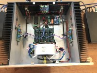
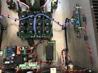
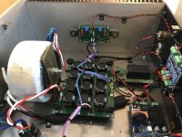
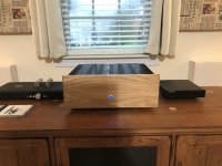
I finished my F5M build and have been listening for a few hours and it sounds outstanding. A huge thank you to Mr Pass and all the helpful members on the forum. I went outside my comfort zone on this build to learn.
I finished my F5M build and have been listening for a few hours and it sounds outstanding. A huge thank you to Mr Pass and all the helpful members on the forum. I went outside my comfort zone on this build to learn.
Attachments
F5M bundles with power supplies are now back in stock in the store, and individual power supplies are also now available.
I finished my F5M build and have been listening for a few hours and it sounds outstanding. A huge thank you to Mr Pass and all the helpful members on the forum. I went outside my comfort zone on this build to learn.
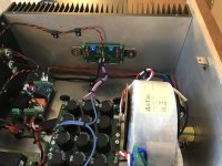
It's difficult to be sure from the photos, but does your transformer mounting bracket and bolt cause a shorted turn?
- Home
- Amplifiers
- Pass Labs
- F5m kit