- I set my gate for nearfield to 999ms
- In addition to the plywood "shelf" you could lightly place a pillow over the port for the woofer measurement and over the woofer for the port measurement. Just don't press so tightly as to prevent the woofer/port from doing what it is supposed to do.

It's undoubtedly in there, but with nearfield methods is hopefully low enough in level that it's not appreciably influencing the measurement. For example, if the background noise is at 60 dB, and your desired signal is at 90 dB, the noise will only increase the level by a tiny fraction of a dB. The lower the desired signal, the more the noise will contaminate it though.Do you think this is getting into the recorded response or does REW do a really good job of removing this
https://sengpielaudio.com/calculator-spl.htm
Averaging helps significantly and is the only way typical software can "remove" noise in the measurements when you are dealing with wideband sources/measurement methods and long windows. It's still there even then, just pushed farther down.
https://www.roomeqwizard.com/help/help_en-GB/html/makingmeasurements.html
"capturing the selected number of sweeps per measurement and averaging the results to reduce the effects of noise and interference. The pre-averaging can improve S/N by almost 3 dB for each doubling of the number of sweeps. Averaging can be useful if the measurements are contaminated by interference tones, whether electrical or acoustic, as they typically will not add coherently in the averaging and hence will be suppressed by the process."
-------------------
Another thing you can do is just take another measurement immediately and see if the frequency response changes appreciably. If it's nearly identical, the noise contribution is likely trivial (unless the noise source is constant, which is not that common in the natural world).
Taking a background measurement of just the noise will give you some idea of the contamination risk also.
I'm not surprised that the measurements are the same. You can't really shield the microphone from the port since the frequencies we're dealing with are so large.Zero difference in response with a plate blocking the port. So I guess it isn't port interference
I can try a 3 inch port. I will model it and set up the print. I am also going to use a different filament type. The ASA has a sort of "ring" to it although it is very stiff. The PETG material is much more "dead" but is less stiff so I will have to make the sidewalls beefier
I was using the PE specs but I modeled it with the website specs that you posted here and it's even worse with a 4" port. It models exactly as your measurements are. There is a massive 6db rise below 100Hz. I highly recommend making a 3" port. It wants to be about 13" long so get as close to that as you can but still make sure that there is a couple of inches between the internal port opening and the back of the cabinet. If you're having noise out of the port then you're going to want to consider some stuffing in the box to knock that down but we can cross that bridge later once the port size is correct.Just want to confirm before i go ahead and print new ports..... did you use the SD off of Parts Express for your calculations?
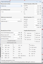
They have the wrong SD there. The SD from the Peerless website is 201. PE has it down as 213
I'm happy to be corrected on this, but where did you find that? The PE website says .66 but the Peerless website says .75It has QTS of 0,54
Yeah I didn't realize I needed to gate that far out for near field measurements.
- I set my gate for nearfield to 999ms
- In addition to the plywood "shelf" you could lightly place a pillow over the port for the woofer measurement and over the woofer for the port measurement. Just don't press so tightly as to prevent the woofer/port from doing what it is supposed to do.
Pillow is definitely a good idea. I don't know how much some 1/4 birch on its own is going to shield when dealing with a 30 hz tone
This is all good info, thanksIt's undoubtedly in there, but with nearfield methods is hopefully low enough in level that it's not appreciably influencing the measurement. For example, if the background noise is at 60 dB, and your desired signal is at 90 dB, the noise will only increase the level by a tiny fraction of a dB. The lower the desired signal, the more the noise will contaminate it though.
https://sengpielaudio.com/calculator-spl.htm
Averaging helps significantly and is the only way typical software can "remove" noise in the measurements when you are dealing with wideband sources/measurement methods and long windows. It's still there even then, just pushed farther down.
https://www.roomeqwizard.com/help/help_en-GB/html/makingmeasurements.html
"capturing the selected number of sweeps per measurement and averaging the results to reduce the effects of noise and interference. The pre-averaging can improve S/N by almost 3 dB for each doubling of the number of sweeps. Averaging can be useful if the measurements are contaminated by interference tones, whether electrical or acoustic, as they typically will not add coherently in the averaging and hence will be suppressed by the process."
-------------------
Another thing you can do is just take another measurement immediately and see if the frequency response changes appreciably. If it's nearly identical, the noise contribution is likely trivial (unless the noise source is constant, which is not that common in the natural world).
Taking a background measurement of just the noise will give you some idea of the contamination risk also.
Yeah I think I should stick with the 8 averages measuring as my default. My shop is on the corner of Elston and Webster in Chicago so there is a lot of noise. I do have acoustic windows and they only do so much. A yoga studio is above me and they walk around incredibly loud. Bare feet on wood floors up there.
The only thing I used off the website is the SD. The rest is pulled from measured Thiele small parametersI was using the PE specs but I modeled it with the website specs that you posted here and it's even worse with a 4" port. It models exactly as your measurements are. There is a massive 6db rise below 100Hz. I highly recommend making a 3" port. It wants to be about 13" long so get as close to that as you can but still make sure that there is a couple of inches between the internal port opening and the back of the cabinet. If you're having noise out of the port then you're going to want to consider some stuffing in the box to knock that down but we can cross that bridge later once the port size is correct.
Attachments
if you can make your own port with 3d printing then reduce the size to tune the port lower like 25 or 30hz.
OK. I didn't realize you had measured for Thiele small parameters. My apologies. My model is now saying a 4" port at 11" long would work. It gives a 3db rise below 100Hz down to about 35Hz, but it looks a lot better to me than what it looked like before. I don't have my PC so I can't model it in Basta to see what your max output is at these low frequencies, but we are within a workable place now in my opinion.The only thing I used off the website is the SD. The rest is pulled from measured Thiele small parameters
Last edited:
Yeah I can make it literally any size I want with any flare, length, dimples, whatever. It does cost like $8-15 worth of filament to make a port though.if you can make your own port with 3d printing then reduce the size to tune the port lower like 25 or 30hz.
TSG,
Let me know if you come up with the same thing. I already designed a 3 inch port. That port length I think will be too long for the area behind the port. Someone gave me a calculation to use for back of enclosure to opening of port. I think the max I can go is 11 inches until I have to start curving it upwards. I can actually curve it upwards I guess.....
Let me know if you come up with the same thing. I already designed a 3 inch port. That port length I think will be too long for the area behind the port. Someone gave me a calculation to use for back of enclosure to opening of port. I think the max I can go is 11 inches until I have to start curving it upwards. I can actually curve it upwards I guess.....
So, I looked at your measurements with the longer gate and that was great advice. I think you're fine with a 4" port as long as you can get it to be 9-10" long (11" is what the model says). If it's easy to make a 3" port at 6" long and try it then it could be fun to see the difference. I will be home tomorrow and I can make a better model in Basta that can show me what your maximum output is and what really is the best port option. I can't do that with my Mac, but the best option is usually the larger port diameter as long as you can get the port to be long enough.
Another thing to consider here about any port leakage. I'm guessing that you're only taking this woofer up to 200 or 300Hz, which is good. The low pass filter will help minimize internal box noise from escaping the port. So, what you're seeing right now on the measurements above 200Hz should change once you have a proper crossover in place. And your box looks well stuffed so even without a crossover, I'm not seeing any bad resonances. That doesn't, however, mean that there isn't a port resonance that will be created. I'm no expert on eliminating those, but flared ports seems to help.
Another thing to consider here about any port leakage. I'm guessing that you're only taking this woofer up to 200 or 300Hz, which is good. The low pass filter will help minimize internal box noise from escaping the port. So, what you're seeing right now on the measurements above 200Hz should change once you have a proper crossover in place. And your box looks well stuffed so even without a crossover, I'm not seeing any bad resonances. That doesn't, however, mean that there isn't a port resonance that will be created. I'm no expert on eliminating those, but flared ports seems to help.
TSG,
I'll print a 3" flared port at 6 inches just for fun. For science....
I'll print a 3" flared port at 6 inches just for fun. For science....
👍I'm happy to be corrected on this, but where did you find that? The PE website says .66 but the Peerless website says .75
Attachments
Bmsluite...
830667 is not well suited for a vented design with a EBP at 56.
Look at the attached picture which contains freefield simulations.
So when placed in a room you will gain bass from room boundaries.
The red line is target curve for combined output for driver and port in a 25 m2 (square meter) room~270 ft2.
The blue line is target curve for combined output for driver and port in a 30 m2 room ~ 325 ft2
With room gain those target curves will have a flat response to 20 Hz in your room.
Light green curve is simulated response from your driver 830667 in a 35 liter cabinet. That's approx 1,25 ft3.
The purple curve is simulated response with a 40 liter vented cabinet as per Parts express recommendation.
That will not work at all. It will give you a very prominent peak of +6 to 7 dB around 30 Hz and way to much bass below 100 Hz.
Simply close the port and elaborate with distance from rear and side walls to find the best tone and resolution in bass response.
If possible, start with 30 inch to side walls and 10 inch between rear of cabinet and rear wall.
Then increase distance between rear wall and cabinet until you find a bass quality you like the best.
Good luck.
Flex,
Yes, I already went through all of this. I purchased it because when I ran sims with the default settings for this driver in WINISD it came back perfectly flat for the box I planned to make.
When I got the driver and took parameters myself I found it to be less than ideal. For my purposes it will work out ok.
WinISD do not add room gain which will increase the bass output.
Depending on the size of your room the boundaries of walls will start to amplify bass from approx. 35-55 Hz.
At 20 Hz room gain usually are 15-22 dB pending on size.
So if you have simulated for a flat response in WinISD you should add room gain.
The best way to handle that is to set up target curves like I have done.
When you simulate and hit these curves you will get a fairly straight response when your speaker are placed in a room.
If you tell me your room size I can simulate a optimization of cabinet volume for your room and 830667.
When designing for a vented cabinet EBP sould be close to 100 to have a chance to get a good bass response.
EBP = Fs / Qes
Last edited:
Well, those are numbers are drastically different than what appears to be nearly the same speaker on the Parts Express. The good thing is that he took his own measurements so that's what we're using now.
Here's a link to the Parts Express specs that are also incorrect. Fun!
https://www.parts-express.com/pedocs/specs/264-1102--tymphany-sls-p830667-spec-sheet.pdf
The room isn't totally square but its basically a 14x18x10' roomWinISD do not add room gain which will increase the bass output.
Depending on the size of your room the boundaries of walls will start to amplify bass from approx. 35-55 Hz.
At 20 Hz room gain usually are 15-22 dB pending on size.
So if you have simulated for a flat response in WinISD you should add room gain.
The best way to handle that is to set up target curves like I have done.
When you simulate and hit these curves you will get a fairly straight response when your speaker are placed in a room.
If you tell me your room size I can simulate a optimization of cabinet volume for your room and 830667.
When designing for a vented cabinet EBP sould be close to 100 to have a chance to get a good bass response.
EBP = Fs / Qes
- Home
- Loudspeakers
- Multi-Way
- Need some help with my woofer and its port. Getting huge rise in deep bass out of this Peerless 8"