
The question here is what is the practical real world advantage ie what audibly can you hear between the high CMRR of a balanced preamp vs a SE one? There’s no doubt if you touched the input of a balanced input you would get no hum (or very little) but on a SE preamp it would be very nousy. But tonearm wiring and turntable to preamp wiring are designed to keep common mode noise to a minimum (small loop areas), so SE preamps if executed well are remarkably quiet. None of this of course should detract from the excellent engineering some balanced designs exhibit, but like chasing ever lower thermal noise, the law of diminishing returns applies.
Hi, sorry, I was busy last couple of days, no time for hobby :-(
@ Mark, It is a good question:
Almost 30 years ago I converted to fully balanced (and differential) system, from beginning to an end, even my main power amp is fully differential.
Before we listened single ended, normal RCA connected stuff, with phone in particular following would occur from time to time, or quite often:
As Hans also pointed out, good CMRR makes it robust to external influences.
But I must admit that this was long time ago, only MM charts were used and probably equipment of that time was much poorer than what I use today.
Also MC system is probably handling most of those issues by dumping unwanted signals over low impedance.
Then it comes RCA connector itself, I still cannot digest that invention, and how it become so popular? Mixing ground connection and signal return current ??? I imagine huge dirty river like Danube (ground), than trow in it crystal clear small mountain spring (signal return), than couple of miles down the water trying to take that spring out of Danube again, I know it is exaggerating, but then again, why to do that at first place?
If someone doesn't fancy Neutrik XLR (which are power connectors of 11 A capability) or are to bulky or expensive, forgotten and super cheap and small 5 pin DIN connector will do, allowing signal and return for both channels in one cable, all separate with separate ground. Also running one ground (instead of 2 like in XLR or RCA) reduces ground loop. Extra L-R crosstalk will be of no harm with phono.
In any case, XLR or DIN, if one doesn't experiment but connects shield directly to the chassis on both sides and treats both + and - (or signal and return) wires as signal (like in any decent pro gear), world makes sense, to me at least.
Then beauty factor, as Hans also said, cart is naturally differential source. I can imagine that micro delicate coil floating in free space connected to the rest of the world just by super thin boron rod as a kind of virgin beauty. Connecting that directly to the ground is like chaining one Tinkerbell's leg to dirty wet dungeon floor full with rats, (now some Tinkerbells might actually like that, but that is completely another book)
Looking from the other side of the coin; what is 3db noise loss? 2 x SSM2017 mic INA preamps (post#32) that I'm using for decades (with direct gain of 60db per leg) have just under 1 nV/sqrtHZ equivalent input noise and that is barely audible if I put ears on my speaker (that is admirably not very efficient) . Paralleling few low noise BJT's will drastically reduce that noise even further, but how quiet do we need? Transistor - resistor noise if at all hear able is not that unpleasant, or is it?
Might be off subject, but what for me degraded sound quite a bit is when I replaced second stage (that was ~ 5kg 2H full chassis + PS chassis version of Pass Balanced Zen preamp) with 50g board hosting 2x OPA2134. 2 vertical switching mosfets (IRF610) are surely not beating 2x OPA2134 neither on THD neither on noise. Only explanation is that I am totally biased on what I built, so it must be much better than OPA.
In summary, at least my view is that externally introduced noises are much more harmful (and stronger) than 3db of transistor noise, that can be avoided by adding more 50cent transistors in parallel. Here I'm not talking only this case but considering also super noisy gain elements like Ga transistors and tubes, even then external induced noise is nastier.
I am sure that fantastic MC system can be built also single ended (especially if battery PS is used and at mains ground is not even connected), but that is covered extremely well here and elsewhere. Than why to do it like that if we can go better with so small extra investment (my comment in post #25)
Fully differential approach is far less covered, hence this thread.
I replied to this question first as it seems quickest thing to do, instead it turned in mini essay with lot of personality 🙂. Scientific or not, this is how I see it.
@ Mark, It is a good question:
I can speak for myself and subjective experiences that are obvious, but don't have measured proof of pudding.I still wonder if there's any advantage to a balanced MC preamp,
Almost 30 years ago I converted to fully balanced (and differential) system, from beginning to an end, even my main power amp is fully differential.
Before we listened single ended, normal RCA connected stuff, with phone in particular following would occur from time to time, or quite often:
- Noise (sometimes loud) when cart (or just tonearm) is touched
- Phantom person talking in quiet room when system is on but not playing, actually Phono preamp become AM receiver 🙂
- Music could sound sometimes sound kind of blurred with same LP playing , later connected with neighbors 4 kW A/C unit that was just ~ 3m away turning on
As Hans also pointed out, good CMRR makes it robust to external influences.
But I must admit that this was long time ago, only MM charts were used and probably equipment of that time was much poorer than what I use today.
Also MC system is probably handling most of those issues by dumping unwanted signals over low impedance.
Then it comes RCA connector itself, I still cannot digest that invention, and how it become so popular? Mixing ground connection and signal return current ??? I imagine huge dirty river like Danube (ground), than trow in it crystal clear small mountain spring (signal return), than couple of miles down the water trying to take that spring out of Danube again, I know it is exaggerating, but then again, why to do that at first place?
If someone doesn't fancy Neutrik XLR (which are power connectors of 11 A capability) or are to bulky or expensive, forgotten and super cheap and small 5 pin DIN connector will do, allowing signal and return for both channels in one cable, all separate with separate ground. Also running one ground (instead of 2 like in XLR or RCA) reduces ground loop. Extra L-R crosstalk will be of no harm with phono.
In any case, XLR or DIN, if one doesn't experiment but connects shield directly to the chassis on both sides and treats both + and - (or signal and return) wires as signal (like in any decent pro gear), world makes sense, to me at least.
Then beauty factor, as Hans also said, cart is naturally differential source. I can imagine that micro delicate coil floating in free space connected to the rest of the world just by super thin boron rod as a kind of virgin beauty. Connecting that directly to the ground is like chaining one Tinkerbell's leg to dirty wet dungeon floor full with rats, (now some Tinkerbells might actually like that, but that is completely another book)
Looking from the other side of the coin; what is 3db noise loss? 2 x SSM2017 mic INA preamps (post#32) that I'm using for decades (with direct gain of 60db per leg) have just under 1 nV/sqrtHZ equivalent input noise and that is barely audible if I put ears on my speaker (that is admirably not very efficient) . Paralleling few low noise BJT's will drastically reduce that noise even further, but how quiet do we need? Transistor - resistor noise if at all hear able is not that unpleasant, or is it?
Might be off subject, but what for me degraded sound quite a bit is when I replaced second stage (that was ~ 5kg 2H full chassis + PS chassis version of Pass Balanced Zen preamp) with 50g board hosting 2x OPA2134. 2 vertical switching mosfets (IRF610) are surely not beating 2x OPA2134 neither on THD neither on noise. Only explanation is that I am totally biased on what I built, so it must be much better than OPA.
In summary, at least my view is that externally introduced noises are much more harmful (and stronger) than 3db of transistor noise, that can be avoided by adding more 50cent transistors in parallel. Here I'm not talking only this case but considering also super noisy gain elements like Ga transistors and tubes, even then external induced noise is nastier.
I am sure that fantastic MC system can be built also single ended (especially if battery PS is used and at mains ground is not even connected), but that is covered extremely well here and elsewhere. Than why to do it like that if we can go better with so small extra investment (my comment in post #25)
Fully differential approach is far less covered, hence this thread.
I replied to this question first as it seems quickest thing to do, instead it turned in mini essay with lot of personality 🙂. Scientific or not, this is how I see it.
A signal wire and its return are not mixing up causing dirty sound. They are usually located close to each other as in a screen and a central core to minimise the loop area at LF. What you do have to do in unbalanced interconnects is keep non-signal related loop currents out of the signal return since if present these will cause voltage drops across the return which then appear in series with the signal. However, in an unbalanced phono amp input, the only interference would be from radiated noise pickup - there are no ground loop currents.
@Bonsai ; first of all I must thank you for at least 3 things:
1. Hifisonix, I guess you are one of its fathers? Beautiful site, long time ago bookmarked, and read regularly
2. For time and effort you put in thoughtful comments on this thread
3. but not least, after +30 years of actively speaking English for work, hitherto you taught me an new word (which is not English only) : stochastic, first time I heard it. Never mind how much one read, there is always a new word to learn!
I will come back soon with some questions on your comments, need some time to do my paper + excel calculations. SPICE never liked me, neither I liked it, even I tried, but damn thing doesn't listen 🙂
Till then:
I do think to understand why preamp likes very low impedance (don't say zero just as we don't like 0 Kelvin). BJT reacts on current anyway, more the better, so from this side I get it. R is directly related to noise, so all ok.
However, my main point is how cartridge behaves on this? This is most difficult one for me to grasp.
You corrected yourself; it is an generator! In early 90's I worked with power generators as it was needed in unfortunate times that then happen here. Generators do not like overload (they don't like under-load neither, 50% to 80% of max power is optimum) , iin high loads diesel driving them must produce much more momentum to keep speed at 1500rpm to keep 50Hz, struggling, vibrating , heating and making noise.
Our LP in rotation+ stylus are diesel engine, coil + magnet a generator. If we decide to take much more power of the generator (which preamp loves) what comes out of cart compliance ? Sure it will stiffen , and this is what is my main consideration, not the preamp.
I'm in process of making model and spreadsheet for 2 cartridges. One like ours (both their Z's are actually quite close, 45(mine) and 40 Ohm(yours)) and other 1n 10,000 € range with Z of 5 Ohm or so. Both driving their recommended load, and current amp's 1-2 Ohms.
PS, How did you measure 30 Ohm R of your Denon coil (As spec Z is 40 Ohm +-20% , guess other 10 Ohms is or Inductance (low at 1kHz) or just tolerance).
My best multi meter uses 14 mV to measure resistance, I'm kind of afraid to apply that voltage ta cart coil...
Of subject: My chart is very well reviewed (as is your Dl103) and it was not cheap at all, I'm looking now at new high end carts, prices went to ridiculousness! When I paid 1k5 Eur, that was half of most ever expensive cart of the time, now that is only 10%
In any case, I will try to make power output comparison.
Cheers
Drazen
1. Hifisonix, I guess you are one of its fathers? Beautiful site, long time ago bookmarked, and read regularly
2. For time and effort you put in thoughtful comments on this thread
3. but not least, after +30 years of actively speaking English for work, hitherto you taught me an new word (which is not English only) : stochastic, first time I heard it. Never mind how much one read, there is always a new word to learn!
I will come back soon with some questions on your comments, need some time to do my paper + excel calculations. SPICE never liked me, neither I liked it, even I tried, but damn thing doesn't listen 🙂
Till then:
I got carried away on spitting at RCA connections in general. , strictly phono (autocorrect always changes phono to phone, sorry for it in other texts of mine) speaking, there is third , ground, cable. But still the screen is the return, just not needed to be like that. Two exactly the same wires , twisted and surrounded by screen are what works with XLR and any proper audio signal routing, at least I think that, as well as most pro audio engineers....... Single core shielded cables are good for HF do, if great distance between core and shield is made. RCA sometime works when all the ground routing maliciously taken car off, but why (me crying why? 🙂)A signal wire and its return are not mixing up causing dirty sound. They are usually located close to each other as in a screen and a central core to minimise the loop area at LF. What you do have to do in unbalanced interconnects is keep non-signal related loop currents out of the signal return since if present these will cause voltage drops across the return which then appear in series with the signal. However, in an unbalanced phono amp input, the only interference would be from radiated noise pickup - there are no ground loop currents.
Until now I did not consider current amps as solution for phono MC, these days I'm trying to catch up on this subject.Drbulj,
In a transimpedance amplifier, the MC cart effectively runs into a short. The cart works like this because in this mode it is being used as a current sensor and not a voltage sensor. You can do this because the cart series resistance is low and the relative currents are quite high (10's of uA). The advantage of this topology is that the only active contributor to noise is rbb' which on transistors like the ZTX851/951 is about 1.4 Ohms each. And if you use a complimentary input stage a la Marshall Leach/Richard Lee/X-Altra MC/MM, the two rbb' appear in parallel, so the total effective rbb' noise is further reduced because the noise sums stochastically.
Your Ruby cart has quite a high internal resistance. I am using a DL103 with my X-Altra MC/MM with the cart test certificate showing 390uV output and I measured the pickup coil resistance at 30 Ohms.
I do think to understand why preamp likes very low impedance (don't say zero just as we don't like 0 Kelvin). BJT reacts on current anyway, more the better, so from this side I get it. R is directly related to noise, so all ok.
However, my main point is how cartridge behaves on this? This is most difficult one for me to grasp.
You corrected yourself; it is an generator! In early 90's I worked with power generators as it was needed in unfortunate times that then happen here. Generators do not like overload (they don't like under-load neither, 50% to 80% of max power is optimum) , iin high loads diesel driving them must produce much more momentum to keep speed at 1500rpm to keep 50Hz, struggling, vibrating , heating and making noise.
Our LP in rotation+ stylus are diesel engine, coil + magnet a generator. If we decide to take much more power of the generator (which preamp loves) what comes out of cart compliance ? Sure it will stiffen , and this is what is my main consideration, not the preamp.
I'm in process of making model and spreadsheet for 2 cartridges. One like ours (both their Z's are actually quite close, 45(mine) and 40 Ohm(yours)) and other 1n 10,000 € range with Z of 5 Ohm or so. Both driving their recommended load, and current amp's 1-2 Ohms.
PS, How did you measure 30 Ohm R of your Denon coil (As spec Z is 40 Ohm +-20% , guess other 10 Ohms is or Inductance (low at 1kHz) or just tolerance).
My best multi meter uses 14 mV to measure resistance, I'm kind of afraid to apply that voltage ta cart coil...
Of subject: My chart is very well reviewed (as is your Dl103) and it was not cheap at all, I'm looking now at new high end carts, prices went to ridiculousness! When I paid 1k5 Eur, that was half of most ever expensive cart of the time, now that is only 10%
In any case, I will try to make power output comparison.
Cheers
Drazen
I have not built a MC preamp, but I did build a balanced MM preamp a few months ago. I noticed the wiring in my turntable was essentially balanced right up to the RCA connector, as it was just separate wires run without shielding. I was seeking to remove the power line noise and the balanced preamp did exactly that. The measured line noise was right at the level of the preamp thermal noise. I wired the preamp with maybe 6 inches of twisted hookup wire to an RCA plug. It works great. I built the preamp with a flat response so I could record the raw signal and then process the clicks and pops and then perform the RIAA EQ digitally. I selected a low voltage noise op amp for the MM input and a low current noise amp for the second stage. For a MC preamp you will want the low current noise amplifier for both stages. As others mentioned LTSpice does a great job of estimating the noise performance of a preamp. I used it extensively to select the parts. Very low resistor values are required to keep the thermal noise of the resistors below that of the opAmp input stage. You can see the spice directives for computing the noise on the schematic. In the end I only built the first stage of the preamp and used the differential line level TRS inputs of a MOTU M4 (inputs 3 & 4) to perform the subtraction and second gain stage.
So the noise floor of the preamp is down about 70 dB from the 1 kHz 5 cm/s level. The surface noise on my records is only down 40 to 50 dB from
the 1 kHz 5 cm/s level. So the preamp is total overkill. The tracing distortion of record playback is at best 0.5% on a 1 kHz 5 cm/s track and goes up from there with rising frequency or amplitude. So the distortion of the preamp is far below that as well.
All that to say, connecting your preamp, whatever it is, to a computer audio interface will help you easily measure the performance of your preamp. I used the Arta software, but REW would work well too.

Two stage MM differential preamp.

As built, single stage preamp for use with differential input USB interface. Omit R17,R18, C4 &C5 for flat response. They were included for noise calculations to mimic RIAA roll off.


The measured performance was achieved with the circuit show above without shielding and using a bench power supply.
So the noise floor of the preamp is down about 70 dB from the 1 kHz 5 cm/s level. The surface noise on my records is only down 40 to 50 dB from
the 1 kHz 5 cm/s level. So the preamp is total overkill. The tracing distortion of record playback is at best 0.5% on a 1 kHz 5 cm/s track and goes up from there with rising frequency or amplitude. So the distortion of the preamp is far below that as well.
All that to say, connecting your preamp, whatever it is, to a computer audio interface will help you easily measure the performance of your preamp. I used the Arta software, but REW would work well too.
Two stage MM differential preamp.
As built, single stage preamp for use with differential input USB interface. Omit R17,R18, C4 &C5 for flat response. They were included for noise calculations to mimic RIAA roll off.
The measured performance was achieved with the circuit show above without shielding and using a bench power supply.
Last edited:
Hi, thanks!I have not built a MC preamp, but I did build a balanced MM preamp a few months ago. I noticed the wiring in my turntable was essentially balanced right up to the RCA connector, as it was just separate wires run without shielding. I was seeking to remove the power line noise and the balanced preamp did exactly that. The measured line noise was right at the level of the preamp thermal noise. I wired the preamp with maybe 6 inches of twisted hookup wire to an RCA plug. It works great. I built the preamp with a flat response so I could record the raw signal and then process the clicks and pops and then perform the RIAA EQ digitally. I selected a low voltage noise op amp for the MM input and a low current noise amp for the second stage. For a MC preamp you will want the low current noise amplifier for both stages. As others mentioned LTSpice does a great job of estimating the noise performance of a preamp. I used it extensively to select the parts. Very low resistor values are required to keep the thermal noise of the resistors below that of the opAmp input stage. You can see the spice directives for computing the noise on the schematic. In the end I only built the first stage of the preamp and used the differential line level TRS inputs of a MOTU M4 (inputs 3 & 4) to perform the subtraction and second gain stage.
So the noise floor of the preamp is down about 70 dB from the 1 kHz 5 cm/s level. The surface noise on my records is only down 40 to 50 dB from
the 1 kHz 5 cm/s level. So the preamp is total overkill. The tracing distortion of record playback is at best 0.5% on a 1 kHz 5 cm/s track and goes up from there with rising frequency or amplitude. So the distortion of the preamp is far below that as well.
In different and more precise words you said exactly what I want to say; differential removes common (external ) noises efficiently due to its high CMRR , twisted wires are better than coax with shield serving as return, inherent LP surface noise is higher than any decent preamp will ever make,
I fully agree with your description of needed opamp types related to input impedance vs eN, Did not study LT1037, but from your description Im sure its right one for MM source.
The point of digitalizing vinyl is another thing, Unless you are archiving original old presses for future generations, why? Just buy download of already digital copy (that is hopefully digitalized from master tape) 🙂
Cheers!
“Our LP in rotation+ stylus are diesel engine, coil + magnet a generator. If we decide to take much more power of the generator (which preamp loves) what comes out of cart compliance ? Sure it will stiffen , and this is what is my main consideration, not the preamp.”
The compliance is unaffected because the generator coil<>magnet coupling is not reciprocal. This was discussed in quite some depth on one of threads that covered compliance iao things.
The compliance is unaffected because the generator coil<>magnet coupling is not reciprocal. This was discussed in quite some depth on one of threads that covered compliance iao things.
Last edited:
Sorry, do you know which thread, Some are on 1000+ pages, not so easy to find thatwas discussed in quite some depth on one of threads that covered compliance iao thing
I think it was in this thread, but I am open to correction
https://www.diyaudio.com/community/threads/mechanical-resonance-in-mms.303389/
Gpapag, a member here, probably has the information from the measurements/discussion or can point you to the specific posts.
https://www.diyaudio.com/community/threads/mechanical-resonance-in-mms.303389/
Gpapag, a member here, probably has the information from the measurements/discussion or can point you to the specific posts.
Hi Hans,A SE input has zero CMRR, a differential input can easily achieve a high CMRR.
A Cart is a perfect balanced source.
As long as the overall S/N with Cart connected including the additional 3dB diff. noise penalty is still high enough, this extra noise won’t have any impact.
Hans
I have always had difficulty in considering carts as a balanced source, rather more as a floating source. This seems no different from considering a battery in free space and considering it as a balanced source. Balancing suggests referencing to a third reference that appears arbitrary. Consider the head amplifier identified as a GyroHead (simply that it self circulates in the balancing). I have been using this for awhile now with a Denon 103r cartridge. Interestingly if the network is reasonably balanced the power switch can be used as a mute switch.
This implementation is reliant upon two independent networks that use non rechargeable 3 volt batteries (CR123A's), one for each channel. These are 1550 mAH, hence should last greater than 500 hours with a 2mA draw.
The caveat is that balanced input cables are required since the network is grounded at alternative points to the four lines from the cartridge. However, in doing so this allows the grounding to be optimized, even split referenced at the op-amp end feeding the RIAA network, perhaps with differential drive. Although noise is a consideration there are advantages in that the network is DC coupled, avoiding the electrolytic coupling components. By the way I am using an LM394 device with an LT1115 as the input to the phono.
Gerrit

Hi,
I think its commonly agreed on that the balanced transmission clearly shows a greater immunity to external noise/disturbance sources.
The Q regarding possible advantages Imho rather dealt with the internal topology of an amp.
If the designer does the gnd layout right -where he has full control of, while with external transmission he doesn't- what could justify the higher effort and parts number count of fully balanced against SE?
jauu
Calvin
The floating GyroHead above was implemented in a separate shielded box with XLR in/out. Without connection to the subsequent phono RIAA amplifier neither right or left channels are balanced or unbalanced as neither has a ground yet connected. This is to state that output current in each channel leaves on one lead and must return on the other regardless of the manner ground is connected external to it, being ultimately viewed balanced or SE. In other words there is no electrical significance to the manner of grounding to the phono preamplifier from the perspective of the GyroHead amplifiers.Hi,
I think its commonly agreed on that the balanced transmission clearly shows a greater immunity to external noise/disturbance sources.
The Q regarding possible advantages Imho rather dealt with the internal topology of an amp.
If the designer does the gnd layout right -where he has full control of, while with external transmission he doesn't- what could justify the higher effort and parts number count of fully balanced against SE?
jauu
Calvin
The extent of immunity is to a degree reinforced in that the 3 Volt battery power supplies to GyroHead amplifier can be turned on an off with full volume and the network mutes with minimal transient artifacts being noticed or realized. In other words the power supply rejection ratio is extreme by the manner in being "floated" with the output signal in the uV levels simply collapsing.
Ultimately immunity to external noise/disturbances is a function of signal to noise ratios. Because the GyroHead has high current gain this can be viewed to "more or less" overwhelm noise/disturbances generated in the subsequent RIAA phono amplifiers (the current design is not suitable for mm cartridges). However this does not preclude considerable care in amplifying and handling the signals in the RIAA phono section being implemented SE. (On a side note the noise generated by the GyroHead can change character dependant upon the manner the RIAA networks are implemented, meaning that the existence of noise can show up having a different spectral character in the audio band even though the frequency response follows the RIAA curve).
The output of the GyroHead/ phono preamplifier combo was designed around the Denon 103R to generate perhaps 6-8 volt RMS to maximize signal to noise ratios without the need to necessarily move to balanced amplification (there is a general trend to increasing signal outputs). Even though the network is SE there can still be an advantage in using XLR's to feed a balanced amplifier. The reason being that the phono preamplifier can have some single point ground being connected to pin 3 of the XLR. The input circuit of the balanced amplifier (in my case a Topping PA5) can use pin 3 as a clean ground referenced signal looking back to the phono preamplifier. This is in contrast to picking up common ground shield noise as part of the signal return path.
From the discussion above it seems there is evidence that the wiring to the cartridge should not be twin coax, but shielded pairs? Keep the shield distinct from the signal wires except at a single ground point. Its not clear to me that you also need differential amplification or floating cartridge signals.
Magnetic coupling into the signal loop is fundamental and already differential, magnetic coupling between shield and signal is eliminated by only connecting shield to signal ground at the preamp side, capacitive coupling to the signal wires is extremely low given the impedance levels of a few tens of ohms, especially if the whole signal path is shielded in some form, tonearm, headshell, plinth case.
What have I missed?
Hi, It makes me very happy that the subject picks up a lot of reaction and very qualified posts! My problem is that now i need to find more time to dedicate as posts deserve it.
Just to summarize, for easier questions that were opened;
1. Low noise devices; here seems to be consensus , lowest Rb devices as ZTX and such
2. Trans-impedance and effects of super low Rin on cart compliance, this seems to be confusion in my head only, working on it...
3, Wiring topology (i fad to invent a name for several subjects) floating- balanced- differential, wiring return path and wiring ground....
True1. Low noise devices; here seems to be consensus , lowest Rb devices as ZTX and such
No effect on compliance from termination, see2. Trans-impedance and effects of super low Rin on cart compliance, this seems to be confusion in my head only, working on it...
https://www.diyaudio.com/community/...vidual-transfer-functions.397815/post-7314673
And
https://www.stereophile.com/content/dispelling-myth-about-phono-cartridge-loading
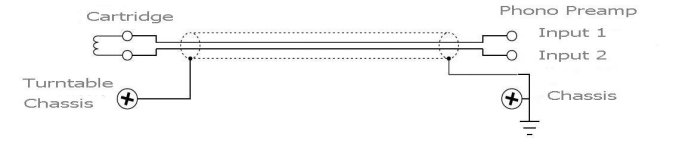
See attachment for balanced connection3, Wiring topology (i fad to invent a name for several subjects) floating- balanced- differential, wiring return path and wiring ground....
Hans
Attachments
Hi Hans,
Thanks for the link on the tread, Ill study that. Looks promising as everyone says it does not effect, I like to hear that.
On many sites , including newish Ron Sutherland's Loco preamp's reviews, many state that it works well with only very low Zout carts, without explanation,,, Among own thinking thats one of reasons to dig into that, besides I have 45 Ohm Zout cart, many people have similar too. Stereophile article I also linked earlier in this tread 🙂
See attachment for balanced connection
Hans

If Input 2 becomes connected to ground and also chassis at the phono preamp end is it still a balanced connection? I can agree that it uses a balanced cable. Grounding input 2 to the chassis neutralizes the effective capacitance between the input 2 signal line and the chassis, being not true of input 1 hence imbalances the characteristic impedances of the two lines along the length. This suggests that to maintain a balanced connection requires equal impedances to ground and the chassis in the phono preamp termination. Don't know if it matters much though, just how it is described.
For conventional cables with a single conductor inside a shield there can be an advantage in terminating cartridge signals into an effective short circuit. Doing so neutralizes the cable capacitance, effectively preventing voltage differentials between the center conductor and the shield with possible consequence of inhibiting dielectric absorption artifacts from being imposed on the signals. This was the reason for terminating the GyroHead into the inverting terminal of the LT1115, to neutralize cable capacitance artifacts as also to widen the bandwidth. Another factor is that this inhibits voltage differences appearing across the base/collector junctions of the LM394 transistors inside the GyroHead as potentially contributing to negative sonic artifacts.
Last edited:
- Home
- Source & Line
- Analogue Source
- Fully balanced MC phono preamplifier thoughts