This post is not how to do stability analysis, but rather did they do a good job of it on these older amps.
==== SOME ONLINE PAPERS AND THREADS
I've decided to add links to some of the papers that we've discussed over the years.
AN2653 from ST Micro on Stability Compensation is attached as a .pdf
There was a lot of talk about "the Gilbert paper" many years ago. There is talk about audio and Otala in this paper:
A member found it online: https://linearaudio.net/sites/linearaudio.net/files/Are Op Amps Really Linear.pdf
Bob C. on how to design MIC compensation:
https://www.diyaudio.com/community/threads/miller-inclusive-compensation-mic-design-example.317147/
Links to discussion about TMC vs. TPC compensation:
https://www.diyaudio.com/community/...tion-tmc-vs-two-pole-compensation-tpc.317330/
==== SOME POWER AMP EXAMPLES
I followed power amp design fairly well through the 60s -90s but didn't have access to many schematics from
Japanese gear so not very familiar with those. I was thinking that there's no clear stability technique used in
many older amps, often caps seem to be sprinkled about in an amp. And why was a Cdom cap so rare, did
they fear that it would harm performance (measurements) or sound? It took a while to think of one amp that
used a Cdom cap, but then of course the RCA reference design (also Harman Kardon Citation 12) came to mind.
==== THE BRUTE-70 FROM POPULAR ELECTRONICS FEB. 1967 BY E. G. LOUIS
https://deramp.com/swtpc.com/PopularElectronics/Feb1967/PE_Feb1967.htm
But let's go back further to the "Brute 70" from 1967, what do you know it has MIC as shown with C4 plus an
output Zobel:
I like this and I hope that it was stable in practice:

==== RCA QUASI COMP REFERENCE DESIGN
Next we have Cdom (Miller) compensation, also C4, in the RCA 1969 reference design and a Zobel:
Good job - I built the HK version which was stable in practice.

==== SWTPC DAN MEYER TIGER AMPS
Everyone has heard of the SWTPC (Dan Meyer) Universal Tiger (UT) 1970 blowing up with lots of smoke:
I don't see any logical compensation scheme here, a Zobel and a cap (C8) on the feedback resistor:

I'll also point out that the Plastic Tiger and Tiger .01 were also prone to blowing up in a similar way with
melted caps.
It seems that Meyer got smart on the Tigersaurus, 1973 that has MIC (C2) and RC (R15 C3) loading on the Vas:
Did he go back and look at the Brute 70 for inspiration? We'll never know.
I built this amp from scratch and it never blew up - nice work.

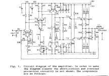
==== PHASEL LINEAR 700 by BOB CARVER 1972
The Phase Linear 700 was the most powerful amp of this time frame at 350W/ch with 100V rail voltages! I was
surprised when I first saw a schematic that it only had 5 output devices per polarity, ten total per channel. After
a lot of thought I concluded that he used some sort of single diffused transistor that were known not to have
(the output are not series connected as was done in most other high powered amps of this time)
SOA issues and would do their rated power at high voltages. He used a Delco electronics XPL909 for outputs
and a guess is that these were developed for the high voltage primary in electronic ignition - a complete guess
on my part. The schematic is essentially the RCA reference design with enhancements as needed for the high
voltage and power. It is a quasi-comp EF triple, how about that? The output current is so high that a triple is
required or at least a good idea. The Vas is boot strapped, probably to avoid another expensive high voltage
transistor. Note the diode protection on the Vas, I'm sure when if these blow up it is an expensive repair so
protection is important. I left out the VI limiting in order to make the signal path more clear. The first version
ran the front end at the full rail voltage, and I'd think that this caused SOA problems in the transistors. He
figured out a clever way to run the diff pair and 2nd stage on 20V supplied by a Zener. This is officially a 3
stage amplifier but the high level of degeneration on the second stage might help in this regard. And, this is
another amp with MIC compensation, a Zobel on the Vas, and a few other compensation networks. It looks as
if some thought went into this design. It does not include an output inductor and I'd expect that capacitive
loads might have given it trouble. Also, without doing the analysis, I'd expect that it would have SOA problems
driving 4 ohm loads, certainly reactive ones. I've seen one in person and heat sinking is quite minimal, fans
that run on temp rise would make a lot of sense. This is redrawn for clarity in SPICE where I chose devices as
close to what was probably used for later repairs at the factory. I am limited to Bob C's SPICE models because
I do not trust others. There are other models checked and fixed by members here but I do not know if every
model in their files have been checked. It does run and the basic operation looks good, I have not checked
for stability:
I know that his later small cube amp had a reputation for blowing up, how about this amp, did it run well at
least into 8 ohm loads?

==== MARANTZ (DESIGNER UNKNOWN)
Marantz M510 from 1976 notice C313 and C314 as speed up caps on the emitter degeneration of the push-pull
Vas, C310 across the feedback resistor, Vas loading C312, and diff pair RC damping with C308. This looks well
thought out to me but I have not analyzed it or lived with one - was it stable in practice?:

==== MATTI OTALA
Here's Matti Otala's (RIP) paper on the theory of TIM distortion Feb 1977, not endorsing this just for historical reference,
note that the schematic for his amp is not in this paper. This paper came later probably to counter the negative
claims toward his work in the early 1970s:
https://hifisonix.com/wp-content/uploads/2017/10/The-Theory-of-TIM-Matti-Otala.pdf
And here is Otala's Feb. 1973 paper with the amplifier schematic:
https://linearaudio.net/sites/linearaudio.net/files/otala low tim amp.pdf
Here's the schematic, note the 3 stages of diff pairs, and C2, C4, C6 as some sort of compensation. R26 and R27 to ground
were a key feature to lower the open loop gain but were controversial. Leach bought into all of this but in the end removed
these resistors from his own designs and employed a Cdom cap. From memory D. Self says, in his book, that he could not
make a 3 stage amp like this stable. I did not hear reports of these blowing up, however note that there's a total of 600mA
in the output transistors make it a very hot amp and there have been reports of burnt circuit boards after 10-20 years.

==== AUDIONICS CC-2 BY BOB SICKLER 1977-78
Lynn Olson writes very highly about this design because he worked at the company designing speakers and Bob Sickler asked
him for realistic dummy loads that he could use to test and refine the design:
http://www.nutshellhifi.com/library/bobsickler.html
He started with a Fairchild app note and was influenced by the Otala TIM frenzy. Olson claims 70V/usec slew rate and 60 deg
of phase margin. Olson writes that it sounded good, sold very well, and had a very low failure rate:
Note the use of paralleled driver transistors for higher current and power:

==== Professor MARSHALL LEACH PhD
Link to .pdf with Leach's original Low TIM amp article in Audio, and all of the many revisions:
https://leachlegacy.ece.gatech.edu/papers/lowtim/feb76feb77articles.pdf
Professor Marshall Leach (RIP) PhD offered a Low TIM construction project in Audio Magazine Feb. 1976 that is simpler,
with fewer stages and more power output: Note that it is quite simple with resistors R20 and R21 to ground at the Vas,
C10 and R33 across the feedback resistor and a Zobel at the output, after the inductor, usually it is before:

The second part of Leach's article came out a year later in Feb. 1977 with a revision to the schematic, MIC compensation
is added through C10 and R33, interesting. Also, Vas and output protection are added:

Next we have Leach's Low TIM Amp II in May, 1978, he's moved to Cdom compensation and removed the resistors to
ground and the cap across the feedback network. The Matti Otala features are gone. Also, he's cascoded the input
diff pair transistor and doubled up on output devices - good since SOA was poor on old output devices. Cdom
compensation should be stable but I don't know if he designed the component values correctly:
As Cordell and Self have shown a Cdom compensated amp can have very low distortion and low TIM:

In Leach's next Low TIM Amp 3, Dec. 1978 we still have Cdom compensation but C11 is added across the feedback resistor,
and capacitors C4 and C5 are added to the diff pair. The main feedback network to the is strange:

Leach's Low TIM 4 amp from May 1986, we have the main feedback from the output shunted at HF through C10.
And then HF feedback is provided from the output pre-drivers through C8 and C9. I've never seen this done before,
and I could see that if it had oscillation when clipping due to the finals slowing down, this circuit instead takes the
HF feedback from the pre-drivers. No idea if this was the reason or if it works well:

==== DEAN JENSEN
Save the best for last ...
The JE-990 (990) OP amp from 1980 by the late Deane Jensen is an impressive piece of engineering. He (his company) designed
this, partly, to help sell their transformers. The 990 was first described in 1980 as a public domain design in the AES Journal:
http://www.technicalaudio.com/pdf/J...ted/Jensen_JE-990_opamp_JAES_reprint_1980.pdf
"JE-990 Discrete Operational Amplifier"
JAES Volume 28 Number 1/2 pp. 26-34; January/February 1980
I simulated it here, with links to John Hardy docs and info:
https://www.diyaudio.com/community/threads/simulation-of-the-je-990-op-amp-by-deane-jensen.107404/
http://www.johnhardyco.com/pdf/990.pdf
I read this article back when it first came out and was impressed with the detailed analysis of the entire design but also especially for stability. Circuit simulation was used to optimize for stability:
From the AES article, R9 and C1 provide Cdom compensation with a zero at 8.1 MHz. A capacitor and series RC network across the emitter of Q6 create two zeroes, one at 3.3 MHz and one at 25.4, and a pole at 5.8. Read the article for the full details.
I'm fairly sure that improved stability can always be provided by an RC for the Cdom network and a small cap across the emitter resistor. Of course it will harm stability if they're not properly designed.
This is not a power amp but notice that the outputs below could be the drivers for a pair of output devices. Stability analysis would have to be redone, of course.

I want to add a few others Ampzilla, Marantz M250, and maybe more down the road.
Almost forgot, if you follow the original Leach amp articles in Audio and the follow updates, you'll see that he
certainly didn't get it right the first time and as I recall there were many revisions to the compensation. I
wonder if anyone has the progression of updates documented.
==== SOME ONLINE PAPERS AND THREADS
I've decided to add links to some of the papers that we've discussed over the years.
AN2653 from ST Micro on Stability Compensation is attached as a .pdf
There was a lot of talk about "the Gilbert paper" many years ago. There is talk about audio and Otala in this paper:
A member found it online: https://linearaudio.net/sites/linearaudio.net/files/Are Op Amps Really Linear.pdf
Bob C. on how to design MIC compensation:
https://www.diyaudio.com/community/threads/miller-inclusive-compensation-mic-design-example.317147/
Links to discussion about TMC vs. TPC compensation:
https://www.diyaudio.com/community/...tion-tmc-vs-two-pole-compensation-tpc.317330/
==== SOME POWER AMP EXAMPLES
I followed power amp design fairly well through the 60s -90s but didn't have access to many schematics from
Japanese gear so not very familiar with those. I was thinking that there's no clear stability technique used in
many older amps, often caps seem to be sprinkled about in an amp. And why was a Cdom cap so rare, did
they fear that it would harm performance (measurements) or sound? It took a while to think of one amp that
used a Cdom cap, but then of course the RCA reference design (also Harman Kardon Citation 12) came to mind.
==== THE BRUTE-70 FROM POPULAR ELECTRONICS FEB. 1967 BY E. G. LOUIS
https://deramp.com/swtpc.com/PopularElectronics/Feb1967/PE_Feb1967.htm
But let's go back further to the "Brute 70" from 1967, what do you know it has MIC as shown with C4 plus an
output Zobel:
I like this and I hope that it was stable in practice:
==== RCA QUASI COMP REFERENCE DESIGN
Next we have Cdom (Miller) compensation, also C4, in the RCA 1969 reference design and a Zobel:
Good job - I built the HK version which was stable in practice.
==== SWTPC DAN MEYER TIGER AMPS
Everyone has heard of the SWTPC (Dan Meyer) Universal Tiger (UT) 1970 blowing up with lots of smoke:
I don't see any logical compensation scheme here, a Zobel and a cap (C8) on the feedback resistor:
I'll also point out that the Plastic Tiger and Tiger .01 were also prone to blowing up in a similar way with
melted caps.
It seems that Meyer got smart on the Tigersaurus, 1973 that has MIC (C2) and RC (R15 C3) loading on the Vas:
Did he go back and look at the Brute 70 for inspiration? We'll never know.
I built this amp from scratch and it never blew up - nice work.
==== PHASEL LINEAR 700 by BOB CARVER 1972
The Phase Linear 700 was the most powerful amp of this time frame at 350W/ch with 100V rail voltages! I was
surprised when I first saw a schematic that it only had 5 output devices per polarity, ten total per channel. After
a lot of thought I concluded that he used some sort of single diffused transistor that were known not to have
(the output are not series connected as was done in most other high powered amps of this time)
SOA issues and would do their rated power at high voltages. He used a Delco electronics XPL909 for outputs
and a guess is that these were developed for the high voltage primary in electronic ignition - a complete guess
on my part. The schematic is essentially the RCA reference design with enhancements as needed for the high
voltage and power. It is a quasi-comp EF triple, how about that? The output current is so high that a triple is
required or at least a good idea. The Vas is boot strapped, probably to avoid another expensive high voltage
transistor. Note the diode protection on the Vas, I'm sure when if these blow up it is an expensive repair so
protection is important. I left out the VI limiting in order to make the signal path more clear. The first version
ran the front end at the full rail voltage, and I'd think that this caused SOA problems in the transistors. He
figured out a clever way to run the diff pair and 2nd stage on 20V supplied by a Zener. This is officially a 3
stage amplifier but the high level of degeneration on the second stage might help in this regard. And, this is
another amp with MIC compensation, a Zobel on the Vas, and a few other compensation networks. It looks as
if some thought went into this design. It does not include an output inductor and I'd expect that capacitive
loads might have given it trouble. Also, without doing the analysis, I'd expect that it would have SOA problems
driving 4 ohm loads, certainly reactive ones. I've seen one in person and heat sinking is quite minimal, fans
that run on temp rise would make a lot of sense. This is redrawn for clarity in SPICE where I chose devices as
close to what was probably used for later repairs at the factory. I am limited to Bob C's SPICE models because
I do not trust others. There are other models checked and fixed by members here but I do not know if every
model in their files have been checked. It does run and the basic operation looks good, I have not checked
for stability:
I know that his later small cube amp had a reputation for blowing up, how about this amp, did it run well at
least into 8 ohm loads?
==== MARANTZ (DESIGNER UNKNOWN)
Marantz M510 from 1976 notice C313 and C314 as speed up caps on the emitter degeneration of the push-pull
Vas, C310 across the feedback resistor, Vas loading C312, and diff pair RC damping with C308. This looks well
thought out to me but I have not analyzed it or lived with one - was it stable in practice?:
==== MATTI OTALA
Here's Matti Otala's (RIP) paper on the theory of TIM distortion Feb 1977, not endorsing this just for historical reference,
note that the schematic for his amp is not in this paper. This paper came later probably to counter the negative
claims toward his work in the early 1970s:
https://hifisonix.com/wp-content/uploads/2017/10/The-Theory-of-TIM-Matti-Otala.pdf
And here is Otala's Feb. 1973 paper with the amplifier schematic:
https://linearaudio.net/sites/linearaudio.net/files/otala low tim amp.pdf
Here's the schematic, note the 3 stages of diff pairs, and C2, C4, C6 as some sort of compensation. R26 and R27 to ground
were a key feature to lower the open loop gain but were controversial. Leach bought into all of this but in the end removed
these resistors from his own designs and employed a Cdom cap. From memory D. Self says, in his book, that he could not
make a 3 stage amp like this stable. I did not hear reports of these blowing up, however note that there's a total of 600mA
in the output transistors make it a very hot amp and there have been reports of burnt circuit boards after 10-20 years.
==== AUDIONICS CC-2 BY BOB SICKLER 1977-78
Lynn Olson writes very highly about this design because he worked at the company designing speakers and Bob Sickler asked
him for realistic dummy loads that he could use to test and refine the design:
http://www.nutshellhifi.com/library/bobsickler.html
He started with a Fairchild app note and was influenced by the Otala TIM frenzy. Olson claims 70V/usec slew rate and 60 deg
of phase margin. Olson writes that it sounded good, sold very well, and had a very low failure rate:
Note the use of paralleled driver transistors for higher current and power:
==== Professor MARSHALL LEACH PhD
Link to .pdf with Leach's original Low TIM amp article in Audio, and all of the many revisions:
https://leachlegacy.ece.gatech.edu/papers/lowtim/feb76feb77articles.pdf
Professor Marshall Leach (RIP) PhD offered a Low TIM construction project in Audio Magazine Feb. 1976 that is simpler,
with fewer stages and more power output: Note that it is quite simple with resistors R20 and R21 to ground at the Vas,
C10 and R33 across the feedback resistor and a Zobel at the output, after the inductor, usually it is before:
The second part of Leach's article came out a year later in Feb. 1977 with a revision to the schematic, MIC compensation
is added through C10 and R33, interesting. Also, Vas and output protection are added:
Next we have Leach's Low TIM Amp II in May, 1978, he's moved to Cdom compensation and removed the resistors to
ground and the cap across the feedback network. The Matti Otala features are gone. Also, he's cascoded the input
diff pair transistor and doubled up on output devices - good since SOA was poor on old output devices. Cdom
compensation should be stable but I don't know if he designed the component values correctly:
As Cordell and Self have shown a Cdom compensated amp can have very low distortion and low TIM:
In Leach's next Low TIM Amp 3, Dec. 1978 we still have Cdom compensation but C11 is added across the feedback resistor,
and capacitors C4 and C5 are added to the diff pair. The main feedback network to the is strange:
Leach's Low TIM 4 amp from May 1986, we have the main feedback from the output shunted at HF through C10.
And then HF feedback is provided from the output pre-drivers through C8 and C9. I've never seen this done before,
and I could see that if it had oscillation when clipping due to the finals slowing down, this circuit instead takes the
HF feedback from the pre-drivers. No idea if this was the reason or if it works well:
==== DEAN JENSEN
Save the best for last ...
The JE-990 (990) OP amp from 1980 by the late Deane Jensen is an impressive piece of engineering. He (his company) designed
this, partly, to help sell their transformers. The 990 was first described in 1980 as a public domain design in the AES Journal:
http://www.technicalaudio.com/pdf/J...ted/Jensen_JE-990_opamp_JAES_reprint_1980.pdf
"JE-990 Discrete Operational Amplifier"
JAES Volume 28 Number 1/2 pp. 26-34; January/February 1980
I simulated it here, with links to John Hardy docs and info:
https://www.diyaudio.com/community/threads/simulation-of-the-je-990-op-amp-by-deane-jensen.107404/
http://www.johnhardyco.com/pdf/990.pdf
I read this article back when it first came out and was impressed with the detailed analysis of the entire design but also especially for stability. Circuit simulation was used to optimize for stability:
From the AES article, R9 and C1 provide Cdom compensation with a zero at 8.1 MHz. A capacitor and series RC network across the emitter of Q6 create two zeroes, one at 3.3 MHz and one at 25.4, and a pole at 5.8. Read the article for the full details.
I'm fairly sure that improved stability can always be provided by an RC for the Cdom network and a small cap across the emitter resistor. Of course it will harm stability if they're not properly designed.
This is not a power amp but notice that the outputs below could be the drivers for a pair of output devices. Stability analysis would have to be redone, of course.
I want to add a few others Ampzilla, Marantz M250, and maybe more down the road.
Almost forgot, if you follow the original Leach amp articles in Audio and the follow updates, you'll see that he
certainly didn't get it right the first time and as I recall there were many revisions to the compensation. I
wonder if anyone has the progression of updates documented.
Attachments

Last edited:

Stability analysis falls under the category of Control Theory and I do have the well known text "Modern Control
Engineering" by Katsuhiko Ogata, but it is difficult to apply to power amp design. I took the course. The book
probably does not cover the more advanced forms such as TMC, TPC, MIC, etc.
I come from VLSI chip design (digital) and power amps are just a hobby for me. We did timing analysis over PVT
(Process, Voltage, and Temperature) to confirm that a design will work under all conditions. Process is the variation
in the silicon fabrication, Voltage is the supply voltage +/-5 or 10% whatever the spec, and temperature, speed varies
a lot with temperature. Do you think that any amp is put into a chamber, run at spec temp and voltage extremes
to verify the design in real hardware? Could shock and vibe it also. This was done to validate Military designs.
There were tube OP amps and of course power amps so stability analysis goes way back but many tube amps had
very poor HF stability - I don't think it was well understood by the average audio designer. There's a lot of monkey
see monkey do that goes on in this field. The Heathkit Williamson amps had terrible stability problems.
I'm interested in any papers on how to do stability analysis with an amp on the bench. This is what Bob C. had
to say about it:
"One of the things I use to determine stability is to feed the amplifier with a fairly wideband square wave and look at the various nodes in the circuit to see evidence of ringing and/or parasitic oscillation. The mere absence of parasitic oscillation is not enough - you need to establish that there is no HF ringing as well. I also do these investigations with differing amounts of closed loop gain. For example, if your amplifier is normally set up for a gain of 20, and you change the feedback resistor so that it has a gain of 10, you would like the amplifier to be still stable; this is an approximate way to verify that you have 6 dB of gain margin.
Similarly, I also experiment with the amplifier using compensation that is lighter than what I will ultimately use, to see if it has margin against instability in that sense as well. Finally, I do look at the sinusoidal frequency response of the amplifier out to very high frequencies. In that test, you want to see little or no peaking just prior to the closed loop frequency response rolloff. One also wants to do this test with a variety of loads connected to the output of the amplifier. It is also important to do some of these tests over a range of powers, since sometimes poles in the open loop may shift as device capacitances and/or transconductances may change a bit with signal excursion.
A rigorous lab test of amplifier stability is always a must."
Published papers have been mentioned on here but I don't have the links handy, and will try to look tomorrow.
It's difficult to figure out whether capacitors are placed and sized randomly or if there is a good idea behind it. At least the main theories about linear feedback loop stability are far older than those amplifiers; Nyquist published his stability criterion (which covers any number of poles) in 1932, Bode published his most well-known book in 1945, the Routh-Hurwitz stability criterion dates back to the 19th century.
Leach's original amplifier used resistor loading of the VAS to set the open-loop gain. The feedback network had a single lead capacitor. Transistor junction capacitances reduced the loop gain to unity. This approach could not have been reliable.
The lead capacitor was then split into two capacitors, one of which bypassed the output stage.
Miller capacitors replaced the resistor loading of the VAS. This was a much more conventional approach.
Ed
The lead capacitor was then split into two capacitors, one of which bypassed the output stage.
Miller capacitors replaced the resistor loading of the VAS. This was a much more conventional approach.
Ed
Off-topic, but - speaking of older amps - I'm looking for spice models for
2SB688 and 2SD718 transistors. Can't find them anywhere...
2SB688 and 2SD718 transistors. Can't find them anywhere...
What? My 50+ year-old amps aren't stable???
My Marantz 1200 has power amp boards that are the same as the Marantz 510 and Marantz 250 power amp boards. I learned this about 10 years ago when I put Leach Amp boards into the 1200. I used PB2 info on DIY Audio to repair it.
I still like the sound.
My Marantz 1200 has power amp boards that are the same as the Marantz 510 and Marantz 250 power amp boards. I learned this about 10 years ago when I put Leach Amp boards into the 1200. I used PB2 info on DIY Audio to repair it.
I still like the sound.
@Duke58
The Marantz 510 and 250 schematics that I've seen are radically different why don't you post the ones that
you're referring to? Or if you have links to them.
I see that you really did convert your 1200 to the Leach design:
https://www.diyaudio.com/community/...ower-amp-boards-and-power-transistors.384916/
It did become stable as Leach perfected the compensation scheme and as the many people here have built them.
Last edited:
Whoa! Hold the phone, Jones! Post number 70: https://www.diyaudio.com/community/threads/marantz-250m-repair.148403/page-4#post-5576664
Why so sensitive? I'm talking about the power amp boards, wondering why you would want to redesign them when the Leach Amp is very similar and I obviously did replace them with Leach designed boards. Marantz 250 is definitely very similar designed, and the 510 isn't much different.
Truth is, I saw some of your earlier postings, which are no longer available on DIY Audio, and was motivated to install the Leach designed boards into my Marantz 1200.
I did not mean to offend you in any way. If anything, I was agreeing with you regarding the stability issue with the Marantz amps.
It's difficult to figure out whether capacitors are placed and sized randomly or if there is a good idea behind it. At least the main theories about linear feedback loop stability are far older than those amplifiers; Nyquist published his stability criterion (which covers any number of poles) in 1932, Bode published his most well-known book in 1945, the Routh-Hurwitz stability criterion dates back to the 19th century.
Yes, good points. I'm just offering my opinion on these circuits, more analysis is certainly required.
We should consider that feedback was invented in the early 1900s turns out, at WPI where I got my undergraduate degree:
"Research engineer Harold S. Black revolutionized telecommunications by inventing systems that eliminated feedback distortion in telephone calls. Born in Leominster, Massachusetts, Black graduated from Worcester Polytechnic Institute in 1921; later he received an honorary doctorate in engineering from his alma mater."
Whoa! Hold the phone, Jones! Post number 70: https://www.diyaudio.com/community/threads/marantz-250m-repair.148403/page-4#post-5576664
Why so sensitive? I'm talking about the power amp boards, wondering why you would want to redesign them when the Leach Amp is very similar and I obviously did replace them with Leach designed boards. Marantz 250 is definitely very similar designed, and the 510 isn't much different.
Truth is, I saw some of your earlier postings, which are no longer available on DIY Audio, and was motivated to install the Leach designed boards into my Marantz 1200.
I did not mean to offend you in any way. If anything, I was agreeing with you regarding the stability issue with the Marantz amps.
Okay no problem. Often, people don't listen to me so very pleased to hear that it all worked out for you, excellent!
I did find your thread with the boards for sale and edited my post, all is fine, thanks:
https://www.diyaudio.com/community/...y-analysis-in-older-amps.414946/#post-7732458
Last edited:
The resistive loading of the Vas was inspired by Otala, consider that he called it a Low TIM amp.Leach's original amplifier used resistor loading of the VAS to set the open-loop gain. The feedback network had a single lead capacitor. Transistor junction capacitances reduced the loop gain to unity. This approach could not have been reliable.
The lead capacitor was then split into two capacitors, one of which bypassed the output stage.
Miller capacitors replaced the resistor loading of the VAS. This was a much more conventional approach.
Ed
Cdom was known very far back but many audio amp designers avoided it for some reason.
The resistive loading just pushes up the Cdom pole frequency, keeping GBW fairly constant. Unfortunately, it doesn’t do anything to improve slew rate which is what really sets the TIM floor. The open loop pole can be above 20 kHz, though. And the driving point impedance for the output stage is greatly reduced. That DOES have other advantages such as reducing the switching (crossover) distortion inherent to a class B stage and retaining a high damping factor when clipping. If I use resistive loading in the VAS I add another gain stage to recover OLG. Not strictly required, as the open loop linearity improves due to the local feedback so there isn’t as much distortion to correct. But it does help, if you can stomach a two dominant pole solution. Some people can’t/won’t. Many of the big makers eventually figured it out.
It is hard to do if one wants wide open-loop bandwidth.Cdom was known very far back but many audio amp designers avoided it for some reason.
The "wide open-loop bandwidth" approach requires tight control over open-loop gain and bandwidth. It also requires pushing the pole due to Miller capacitance to a very high frequency. I spent some time in the 1980s making this work well.
In contrast, augmenting the Miller capacitance for the dominant pole requires tight control over gain-bandwidth product and an adequate slew rate. The open-loop bandwidth becomes irrelevant. That is easier.
Ed
Very few of the early transistor amp designers had well thought out stability schemes. Among the true gurus were Great Guru Baxandall, Arthur Bailey and later Edward Cherry.
Among the snake oil merchants were Otala and J Linsley Hood. ALL of Otala's designs, especially the commercial ones he was involved with, had icky stability with real loudspeaker loads. I met both him and JLH in person and was shocked that they just fudged things by trial & error like most of us.
But there are good & bad trial & error methods for stability and using one of the good ones was often better than religiously following your pet theory. Cdom is probably the easiest method to get right and used in many amps from the early RCA & Motorola application notes to the early transistorized QUADs, Leaks, Radfords & loadsa Japanese amps.
The true gurus were all heavily involved in Valve amp design too. The Williamson remains one of the most icky Valve amps .. especially for stability. The Mullard 5-20 and its many variants used one less 'gain' stage for even better performance and stability with much reduced cost & complexity.
Baxandall started a big series on stability in Wireless World but never finished it. Cherry published quite a lot.
The resistive loading just pushes up the Cdom pole frequency, keeping GBW fairly constant. Unfortunately, it doesn’t do anything to improve slew rate which is what really sets the TIM floor. The open loop pole can be above 20 kHz, though. And the driving point impedance for the output stage is greatly reduced. That DOES have other advantages such as reducing the switching (crossover) distortion inherent to a class B stage and retaining a high damping factor when clipping. If I use resistive loading in the VAS I add another gain stage to recover OLG. Not strictly required, as the open loop linearity improves due to the local feedback so there isn’t as much distortion to correct. But it does help, if you can stomach a two dominant pole solution. Some people can’t/won’t. Many of the big makers eventually figured it out.
Yes, we've talked about the resistive loading for years.
Is there an online schematic of an amp that has a clean implementation of what you are suggesting.
The resistive loading just pushes up the Cdom pole frequency, keeping GBW fairly constant. Unfortunately, it doesn’t do anything to improve slew rate which is what really sets the TIM floor. The open loop pole can be above 20 kHz, though.
Indeed, see also https://linearaudio.net/sites/linearaudio.net/files/volume1ltemvdg.pdf
And the driving point impedance for the output stage is greatly reduced. That DOES have other advantages such as reducing the switching (crossover) distortion inherent to a class B stage and retaining a high damping factor when clipping.
How does it reduce crossover distortion? I would expect it to get worse. At least when there is a true dead zone due to underbiasing, the equivalent dead zone at the input gets larger as the open-loop voltage gain from the input of the amplifier to the input of the output stage is reduced.
wg_ski may have meant that low driving impedance reduces distortion due to mismatched Hfe in the NPN/PNP pair.
Ed
Ed
No, the actual crossover distortion. I suppose it also matters whether the dead zone is all dead or mostly dead. Even if it’s mostly dead with a small bias there is a contribution to crossover distortion from the nonlinear input capacitances. Gets worse with those older rugged TO-3s often used in vintage equipment. That goes down when driven from a lower impedance source. The overall residual for the amplifier may not improve %-wise, but the distortion physically generated by the stage is reduced (before global feedback). That tends to improve the spectrum.
That's rubbish.No, the actual crossover distortion. I suppose it also matters whether the dead zone is all dead or mostly dead. Even if it’s mostly dead with a small bias there is a contribution to crossover distortion from the nonlinear input capacitances .... That goes down when driven from a lower impedance source. The overall residual for the amplifier may not improve %-wise, but the distortion physically generated by the stage is reduced (before global feedback). That tends to improve the spectrum.
When you drive a Class B output stage with Lo Z (which is sorta the common Cdom case at least at HF), the distortion mechanism is d(Gm) which is really icky. Self gives a comprehensive but incomplete survey of what happens and IIRC, there have been threads here which extend this.
Driving with Hi Z, the distortion mechanism is 'simple' d(Hfe) which is ALWAYS much lower order and easily made invisible by the increased feedback.
Ed Cherry has several papers on this and also experimental results which I've confirmed in real life.
Resistive loading on the VAS is yucky on so many fronts. You can always achieve BETTER results, both in % THD as well as the yuckiness of the THD residual, with simpler methods and less bits.
- Home
- Amplifiers
- Solid State
- Power Amp Stability Analysis in Older Amps