Qualio does something similar with apparently pleasing results. https://www.qualioaudio.com/products/qualio-iq-1A neighbour is trying to convince me to package protect for mounting open baffles above the bass cabinet… with a wider and less deep bass cabinet below, on which the open baffle can sit. Like Wolf Van Langas.
Rregarding the bass enclosure, i prefer some width as the air movement from inside cone is not so hindered.Have some good news today. Finally have two 10-inch Purifis with four matching passive radiators coming. This means I have to lock down the bass cabinet design. Present cabinet design is only a bit wider than the drivers, but is fairly deep, with the passives on the side.
My plan is a full Purifi build with 6.5-inch M's and the coming tweeter in a smaller but also relatively narrow cabinet sitting on top of the bass cabinet.
A neighbour is trying to convince me to package protect for mounting open baffles above the bass cabinet… with a wider and less deep bass cabinet below, on which the open baffle can sit. Like Wolf Van Langas.
Any feedback from anyone here based on your experience? Should I stick with what people I know personally have already done… relatively narrow but deeper cabinet with passives on the side for the Purifis… or what about a wider but not so deep solution???
For the midrange / tweeter enclosure i would seek a width so that the diffraction bump does not coincide with a spl bump of the driver. Yet also enough rounding/chamfering to reduce the diffraction effects.
Play with Vituixcad , it gives a quite good indication.
The system in pureacouratesound.com the design is quite narrow actually.
Well, this is fascinating. I've never done a measurement like this. Here's the result. Seems like the low end is actually quite even in the omni-directional area.May I suggest, if you are not able to complete a ground plane measurements, or a mic-in-the-box measurement, as suggested by @lrisbo , consider alternatives to do bass response measurement that doesn't include the effects of your room, but includes/ incorporates both the midwoofer AND passive radiators.
One way to do this, is to place your microphone equidistant from all three sound sources-
As you have your MW on the front panel and PR on the side panels, find the point equidistant between the passive radiators- hopefully they will coincide with the centre point of your midwoofer. Next measure the front the back distance between your woofer and passive radiators. The intersecting line between these should be equidistant between all three. This point is INTERNAL to the cabinet.
Now imagine a point external to the cabinet. This point will be above (or below) your speaker cabinet. The levels will be different depending on whether you choose the top or bottom panel. But you're interested mainly in the shape of the response. So you can choose either, for convenience. Place the tip of the microphone there, about 5-10mm away from the cabinet panel, and perform a measurement at a practical level eg.
(at -20dB FS/1V to avoid overloading your microphone)
This is a close approximation of the 2i anechoic response (before considering baffle diffraction losses) from 10Hz to about 150Hz, before the drivers become directional.
Edits: spelling/grammar for clarity
Attachments

Speakers are a few feet from the walls, but it's a tough room so there's a lot of increased energy below 100Hz. The crossover between the tweeter and woofer is around 1.5Khz. But for the Bliesma, the FS is 800Hz and I'm about 27-30db down there since the tweeter is padded by about 12db and it's another 15-18db down from there. So, the tweeter is not -6db at 1.5Khz, it's actually more like -18db there. This gives plenty of protection. This tweeter can easily handle it. I've run this speaker into clipping and the woofer gives out long before the tweeter is even close to having problems.That's a good goal to have in a high-fidelity loudspeaker.
How close to the nearest wall will your speakers be situated?
Your crossover frequency for the Bliesma T34B seems to be set at about 1.5kHz, and the filtered response is –6dB at that point. That's probably about as low in frequency as is prudent. Bliesma's power handling measurements are taken with a 2nd-order 12dB/octave high pass filter set to 2.5kHz. The T34B-4 has a quite high sensitivity of 97.5 dB at 2.83V/1m, so it is likely to have needed a bit of attenuation to blend in with the woofer. That will help protect it from excessive power input when used with a lower crossover frequency.
Nice. the difference between this measurement and your post #2541 is baffle step. The transition from 2-pi to 4-pi, (hemi-spherical to spherical).
It's a good goal to have in a loudspeaker since it better translates to the listening curves above once the speaker is interacting with the room. This is why the klippel is so telling how a speaker will act in a variety of listening environments. Flat anechoic speakers will generally give a downward trending slope in a room plus the room gain gives us more bass which coincides to listeners preferences. So, starting flat with a speaker is the goal.That's a good goal to have in a high-fidelity loudspeaker.
---
Actually not a good goal. Listening tests tell that we humans prefer non-flat spl response at listening spot. Flat in nearfield 0,5-1m would be ok.
View attachment 1331640
Yes, which reaffirms what I'm hearing vs. what I'm seeing in the measurements. I would imagine that if I took many measurements throughout the room, it would look more flat. CheersNice. the difference between this measurement and your post #2541 is baffle step. The transition from 2-pi to 4-pi, (hemi-spherical to spherical).
@ThatSoundsGood When you perform the measurements of the loudspeaker (on the tweeter axis I assume), do you apply a window to the measurements to remove the room reflections of sound that are typically captured in an impulse response? I am asking as your measured curves that I have seen look a little rougher through the crossover region and at higher frequencies than I might have expected.
I do use gated measurements when I'm designing the crossover in the mid/high region, but (obviously) not when I'm mostly looking at low frequency stuff. I also don't gate a lot of the time because even with reflections I can get an idea of what's going.
 Here's an example for you.
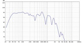
That looks like a very good result: ±2dB around the 90dB level between 400Hz and 20kHz. It looks like you've achieved 3rd-order acoustic roll-offs, so the crossover region is relatively narrow, which is likely to be beneficial as the dispersion is better controlled. Also, the −6dB level at the crossover point indicates an in-phase crossover network, so the main radiation lobe is pointing directly forward.
The small dip around 3kHz is possibly due to baffle diffraction at the cabinet edges. Have you considered placing some felt or other type of acoustic absorption material around the tweeter so as to reduce the intensity of diffraction effects? Something like that shown below might help to get the full, unadulterated potential of the T34B-4 to your ears.

The small dip around 3kHz is possibly due to baffle diffraction at the cabinet edges. Have you considered placing some felt or other type of acoustic absorption material around the tweeter so as to reduce the intensity of diffraction effects? Something like that shown below might help to get the full, unadulterated potential of the T34B-4 to your ears.
It's stylish but the wide open baffle section is going to severely limit the range of dipole radiation this speaker can provide. This wide baffle is even more silly an idea if they are running the planar tweeter open back.Qualio does something similar with apparently pleasing results. https://www.qualioaudio.com/products/qualio-iq-1
View attachment 1331752
They need the baffle to be as narrow as possible and to be stepped so that it gets narrower around the tweeter too.
Yes on all fronts to what you're saying, except for the felt as I don't like how it looks. I made the cabinets with a 1.5" roundover in order to control diffraction (no small feat with a hand held router and solid oak baffles) and I'm still having some diffraction artifacts, particularly the 4db swing from 2.5Khz to 5.5Khz. But that was ultimately a compromise with the off-axis measurements to make the in-room response better. I was able to get it flatter on-axis but it was worse off-axis so I stuck with this final result, which I'm happy with.
I can understand not wanting to put the felt absorption material on the front baffle, as it would definitely not improve the aesthetics of your very nice cabinets. The 1.5" roundover will help to reduce the severity of the peaks and dips caused by cabinet diffraction.
If you are inclined to do so and have some felt or felt-like material of a suitable thickness lying around, you might consider temporarily affixing some absorption material and redoing the measurements that you presented above. That could help to confirm, or otherwise, whether the peaks/dips that are present are largely due to diffraction effects.
If you are inclined to do so and have some felt or felt-like material of a suitable thickness lying around, you might consider temporarily affixing some absorption material and redoing the measurements that you presented above. That could help to confirm, or otherwise, whether the peaks/dips that are present are largely due to diffraction effects.
@witwald: I have yet to see proper evidence, that felt on the front improve diffraction effects of tweeter. There is one simple study about it here: https://audioxpress.com/article/Diffraction-Doesn-t-Have-to-Be-a-Problem
I guess some felt between drivers in some situations may be good. But in the whole I think study is flawed in the way that one measurements on axis says nothing about actual dispersion.
Commercial use of felt around tweeter example in Wilson Sasha show ragged response on the graphs:
https://www.stereophile.com/content/wilson-audio-sasha-wp-loudspeaker-measurements
Im curious if it is actually working or it is more a myth going on.
I tried the felt ring that Madisound sells around a CSS LDX25 tweeter. The tweeter was flush mounted in an 8.5" wide baffle with a 1/2" roundover. The felt changed the frequency response for sure but it was less flat. It made a 2db dip between 4kHz and 6kHz plus reduced everything above that by about 1db. I tried some other versions of felt and it never seemed to flatten the frequency response more so I never tried again. I've attached 2 measurements here. They were taken at 1 meter on axis of the tweeter and the only thing changed was placing the felt around the tweeter.
Attachments
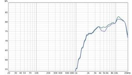
Thanks for sharing the measurements. The simple felt ring does make things worse. Maybe that's largely due to the circular shape, which if the felt isn't all that absorbing adds a strong early reflection to the tweeter's sound radiation. Would a circular arrangement of triangular shapes perform better? And possibly a thicker amount of felt, as the example provided seems relatively thin.
If the felt is actually absorptive then it can have a positive effect on diffraction. Most felt that looks good is quite hard and is actually reflective so it gets worse.Im curious if it is actually working or it is more a myth going on.
The Wilson star approach can create a chaotic diffraction pattern that may or may not have a positive effect.
I don't think it's the circular shape, but I don't really have any proof of that. I did try some other felt that was square. I cut it and applied it in several different ways to the baffle, but it never gave satisfactory results and never did much below 4Khz. I think the big problem is actually the thickness (or lack of). We know how thick room treatment needs to be so I would imagine that you would need 1/2" or maybe even 1" thick material to really help flatten things out.Thanks for sharing the measurements. The simple felt ring does make things worse. Maybe that's largely due to the circular shape, which if the felt isn't all that absorbing adds a strong early reflection to the tweeter's sound radiation. Would a circular arrangement of triangular shapes perform better? And possibly a thicker amount of felt, as the example provided seems relatively thin.
Another thing to mention is that it's highly debated whether we can even hear the diffraction. I recently read a study where minimizing edge diffraction didn't result in a higher listener preference. I know that it certainly isn't worth putting felt on a speaker because it just looks so terrible.
- Home
- Loudspeakers
- Multi-Way
- Exploring Purifi Woofer Speaker Builds