Getting there


How bad is this?
This sim is a folded pipe and reversed driver. I would fold this so that the back of the driver and vent share the same exit. I'll try modelling the same pipe but will try using the TH models to make that happen
How bad is this?
GMA tapped variant of any of these is folded such that the backside of the driver is tapped in at some point with the basic TH filling in the TL's 3rd harmonic dip.
This sim is a folded pipe and reversed driver. I would fold this so that the back of the driver and vent share the same exit. I'll try modelling the same pipe but will try using the TH models to make that happen

I stole this from somewhere (maybe from @LORDSANSUI ) in this forum while back? I Wondered if changing the flare to ‘exp’ might resemble the flared plastic ports/we can purchase or 3d print
Attachments
Last edited:
I stole this from somewhere (maybe from @LORDSANSUI ) in this forum while back? I Wondered if changing the flare to ‘exp’ might resemble the flared plastic ports/we can purchase or 3d print
Booger
I just ran that sim with the ZXI12.4D driver, but the low Vas, high Xmax problem with aspect ratio persists. Due to the small Vb, ports become TLs. So, I tried to figure out how to turn that last clean TL into a TH. by getting the mouth to eat the tail
I think I have worked out how to use system model components correctly for this speaker. That H3 that I added as a flared scoopy looking exit mouth to turn that into a TH cleaned up the big peaky dip between 150-200Hz and takes up almost 30 new litres, but an actual fact does not increase the footprint or height as they form shrouds for the reversed driver. This should look like a scoop with the driver not on the face but in the scoop and in the correct plane to avoid sag
Don't really have the experience to make a confident call, but this seems low and flat in a very small cab, and the best high range that I could pull out of this driver. It's a lot less sensitive than the driver in your example and a lot smaller, but it is a 16kg driver and can soak up some power, so should be loud enough for my needs. Especially with 4 speakers all up
I don't know how good or bad this is for my first attempt at a TH but between this, the TL and the best of the BR from WinISD, I should have something that works okish
Will port this TH and the TL over to my sound system project as potential subwoofers. The bass reflex is the smallest of the trio due to the other two being more true TLs but if it can hold its own as the floor monitor than it gives me the set of cabs to kick off my project
Next up is drawing up the three test boxes designed for disposable MDF offcuts
I copied a lot of @GM advice/ideas over the last couple years for tapped tapered tubes and qw stuff…. They always sound pretty good

Is that what I simmed up/as Opposed to annoyingly aweful (high order qw) 🤓
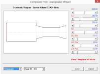
To judge any simulation we need to see the box geometry, in this sense we can crosscheck HR inputs and model precision.
Folding any segment will require the use of "advanced center line" method.
If the simulation matches the Box Geometry you have a good candidate to build.
Folding any segment will require the use of "advanced center line" method.
If the simulation matches the Box Geometry you have a good candidate to build.
o judge any simulation we need to see the box geometry, in this sense we can crosscheck HR inputs and model precision.
Do you mean the input screen? This is the TL that I am working on. I don't really have the experience with the sims to tell if this is a good result, but from what I can interpret, It's not too bad for a TL subwoofer for the size of the cab. I did detune it to a higher Fb than what can be had with this driver in a lil larger TL. I don't need anything below a good 5-string bassline and happy to trade off extension for a shorter pipe. This one will be used to monitor an electric bass and a keyboard synth as a standalone 2.1 ina cab format. Looking for a clean response under 100hz here, as will cross to the 2.0 drivers there.
But if this is valid, it would be ideal for my main subs for the sound system
To judge any simulation we need to see the box geometry, in this sense we can crosscheck HR inputs and model precision.
In general the geometry is checked from CAD or any other sketch with box dimensions.
Sometimes what you input on Hornresp might not be feasible in the real world, or not precise, so crosscheck is important.
For all those models available in the website you can download the CAD file.
Ah, you mean the GA. Doing one in FreeCAD. Trying to avoid flat panel construction, instead leaning towards FRP composite. What this means is that the limits imposed by furniture making practices do not apply. For this build. I do understand what you mean though and have been keeping close tabs on how the acoustic model proportionsIn general the geometry is checked from CAD or any other sketch with box dimensions.
Sometimes what you input on Hornresp might not be feasible in the real world, or not precise, so crosscheck is important.
I have been splitting an elbow in half and rotating one of the halves to convert a bend into a straight for calculations. Would this be sufficient?Folding any segment will require the use of "advanced center line" method.
If the simulation matches the Box Geometry you have a good candidate to build.
This is my study after evolving the boxes as much as could. The segment Sd are kept small to see if I can get away with them with the test box. Hornresp calculates 34hz Fb but in the 3D model, extra pipe length will be allowed to correct for bends, fillets and other air noise prevention things and hopefully hit Fb targets or better
Can anyone see any remarkable issues with the sims? They look flat to me, but do you folks see any potential for poor sound quality in the acoustic models?
That big flare in the TH is really for aesthetic reasons to give the box a scoopy look for ambience by using the driver location as a useful visual feature. A lot of this effort is to engineer it so that aesthetics isn't gained at the expense of performance, but rather build performance. Removing that does not change the box physical size and becomes the TL model in the last pic
Full details are in the pics if anyone else can make use of this box or curious to mess with the sims
-
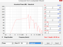
This above pic is with filters off and on, no eq. I don't know what the 4th order business is yet but looks good. Delay goes up a lil bit but mostly in the subsonic. But it does show a good unfiltered and lots of scope for shaping sound with DSP.
The next pics are the same cab without those side panels and as a TL. Again with the filter on and Orr. To be honest, I can't tell which of them is the better approach
Some advice would be greatly appreciated. Do either of the models predict a clean sound when compared to the BR system?
looking at the shown impedance curve.
Looks somewhat close to possible alignment.
Usually if the second impedance hump is much higher than
the first.
It is a indication that the system is tuned too high or above Fs.
The transfer functions of both examples curve upward
in the lowend which indicates also high tuning.
And likely possible volume is too large.
Indication of too large of box also visible in impedance curve.
If the dip in between the 2 impedance peaks is not very wide.
The volume would be too large.
The speaker suspension is not ideally happy.
Box seems large and tuning is made high too compensate.
The overall lose of control will show a peak in the lowend.
When ideal it should match a filter alignment/ transfer function.
and have a actual smooth downward roll off.
Hence the whole basics to theile small theory.
If the speaker suspention is happy and tuning is close to Fs
it gives ideal performance and will match a filter transfer function
roll off. With no odd peaks or high Q
The 2 impedance peaks should be roughly equal in impedance.
Which indicates the suspension is happy in the volume it operates.
And tuning is not too high or low.
Noted. I did run a higher tune for shorter horn length. Will make some changes
Thanks for explaining some things
That's the displacement graph, but the impedance is also a taller peak on the lower frequency side, as you say. This was a deliberate attempt to tune higher, but I didn't understand the implications you mention when I did that. Thanks for the education, will make some changes. What does equal tall sharp impedance peaks mean vs low rounded ones?looking at the shown impedance curve.
Thank you for explaining how to read this. Will make some changesThe speaker suspension is not ideally happy.
Box seems large and tuning is made high too compensate.
The overall lose of control will show a peak in the lowend.
I haven't been able to understand what is high Q and how to spot itIf the speaker suspention is happy and tuning is close to Fs
it gives ideal performance and will match a filter transfer function
roll off. With no odd peaks or high Q
The 2 impedance peaks should be roughly equal in impedance.
Which indicates the suspension is happy in the volume it operates.
And tuning is not too high or low.
Thanks for explaining some things
Can anyone see any remarkable issues with the sims
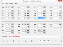
As I mention, without looking to your geometry is hard to check.
You need to post a drawing/sketch so people can see the box layout, dimensions, where driver is placed, and so on.
The simulation looks strange for TH, in general they have positive flare, so S1<S2<S3<S4<S5, while in your case you have negative flare for H1 and H2 segments, H3 is constant and H4 has positive flare.
At some point those numbers from Hornresp simulation will need to be translated into a geometry to build the box and sometimes they are not feasible.
Low Qt (over-damped = transients can't reach peak, ergo rolls off too early) - transient perfect = 0.5 Qt = flat response - high Qt (under-damped = transients shoot past peak, 'ringing' ergo peaking)I haven't been able to understand what is high Q and how to spot it
Note that HR doesn't factor in all acoustic loading as shown in measurements, so minor impedance peaking will be rolled off, though yours are extreme enough to agree with WD 'in toto'. 😉; ergo if all is ~flat it would actually be a slightly to strongly under-damped response depending on (long time) power demands due to VC thermal power distortion increasing its system Qt.
Normally not an issue for HIFI, most HT apps, but for prosound it must be factored in.
The transfer functions of both examples curve upward
in the lowend which indicates also high tuning.
And likely possible volume is too large
These below are the basic BR and TL that I am trying to give a cosmetic scoop look without damaging response and keeping the driver reversed for another cosmetic effect. It's not critical to achieve cosmetic effect but very desiredAt some point those numbers from Hornresp simulation will need to be translated into a geometry to build the box
Low Qt (over-damped = transients can't reach peak, ergo rolls off too early) - transient perfect = 0.5 Qt = flat response - high Qt (under-damped = transients shoot past peak, 'ringing' ergo peaking)
if all is ~flat it would actually be a slightly to strongly under-damped response
Guys
Would you be able to point out these effects on a graph? Not knowing what such products look like on the screen is debilitating when trying to fathom what you folks are saying
Please help understand what those peaky dip things are in these example pics below, and are they a concern?
Is this the good kind of transient response and roll offs?
Fill dampening to reduce the peaks?
I hope to get at least one box ready and tested for use by August so as not to miss an opportunity to hear it in use in the professional conditions of Brolga theatre, which is our performance arts theatre for the Fraser Coast. It's a rare opportunity to observe a bit of DIY gear in such an environment. Please help understand if these model responses are concerning and understand what needs cleaning up
My basic BR with Vb=Vas and FB=Fs. This what I have been trying to give a cosmetic very large flare exit to, and the basis for the original post in this thread. This is unfilled, unmasked, unfiltered and without Eq. The BR sim gives this note in red, which I don't understand
My basic TL, 3 stepped segments, S1=150x65mm, S2=100x65mm, S3=80x65mm, Vtc=4L. I am really attracted to the TL idea as a crazy tiny labyrinth like this with a huge driver sticking out of it would be cool, and I would build this over the BR if this can be a legit candidate. I'll upload full construction and model input data and methods as a DIY musical multi instrument amplifier to share back everything I have learned from you guys to make a better cab
Attachments

- Home
- Loudspeakers
- Subwoofers
- Flared BR ports with Hornresp?