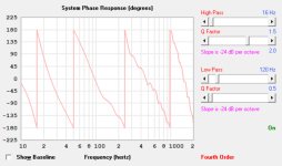
I ?think? the ‘back pressure’ from the rear output placed in the exit (that small 6th order series chamber) will misalign the anticipated driver offset positions intention (1/3 to fix that second resonance and notch above it in a ‘normal’ qw pipe ?
I tried this before and really boogered up the response in that area(looked like Arts original simulation in that area that was suppose to be smoothed out) .
it was much better as an appropriate tapped/tapered(shorter) QW tube avoiding the need for the ambiguous ‘driver offset position’ to clean up lower(longer) pipe resonances?
It seems offset tapped pipes need a lot of ‘tuning’ after the fact to align resonator shapes already dedicated in glue/wood? Paraflex, for example ? That area(above 3 x Fb) is always plagued with mayhem
To see what happens, man! Is this not reason enough?Nevertheless, Why would you put a 12” sub in a 130 cm2 tube that long and twisty? Vent speed and noise and ??? No bass.
It's less twisted than the one @BP1Fanatic drew up for the ZXI
I am leaning on that actually, remember the 15.6L Vas to address? It's going to be a gamble that may or may not pay offI ?think? the ‘back pressure’ from the rear output
It seems offset tapped pipes need a lot of ‘tuning’ after the fact to align resonator shapes already dedicated in glue/wood
A lot of tuning with fill too, but Booger, there is a flaw that you haven't picked up on. Doesn't look like Art has either
The input screen shows only 3 segments and one TC in end to end connected setup. Look at the labels in his input screen, they are not red. That cannot be tuned the way the stepped connection in my input screen can. My FreeCAD template allows this and can be adjusted in the already built box. Arts end to end connection doesn't allow this type of using after the fact of gluing
The second and massive flaw is that you guys assumed a horn exit from the lateral cross-section sans side panels drawing. There are no sides at the driver mount location in the input parameters. The input and the drawing show a port very close to the driver, but the driver is not in a horn as such
To see a tapped model, you must add a tapered segment to S4S-S5. This covers the sides of that horny looking scoop or scoopy looking horn and select the TH 1 model (not TH1) for the response below (with dampening)
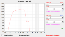
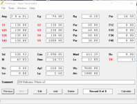
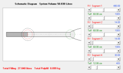
Hornresp falters here, the pipe Sd is 130 constant and segment 2 and 3 are connected together making a 1.2m pipe. Now adjust the lengths in Loudspeaker Wizard while having the response graph up. Hr keeps the 1.2m length while adjusting and shows a change in response even though it's still a constant 130 over 1.3m and don't say because of the bends as there is no input parameter for fold. HR does assume a pipe
Last edited:
Adjusting L12 shifts the first tap point, causing the response to change, even though L12 + L23 remains constant.Now adjust the lengths in Loudspeaker Wizard while having the response graph up. Hr keeps the 1.2m length while adjusting and shows a change in response even though it's still a constant 130 over 1.3m
Makes sense nowAdjusting L12 shifts the first tap point, causing the response to change, even though L12 + L23 remains constant.
I have been able to further reduce the external volume without losing the response. Well maybe I cant tell the difference between the results due to how graphs are compressed in a tiny window
From what I can see, 1/3 offset places the driver on segment 2 entry. So I dropped the TC to inlay the driver on segment 2 side wall at the start. Doing this lifts the Fb by 5Hz but the imp nipples were level even though this was 6Hz above Fs. Adding 50mm to each segment drops Fb back to 32Hz buy with a net saving of 310mm dropped from the cab height
I am now inclined to reduce panel thickness to 12 or even 9mm. The 9mm would be 8mm marine ply with biax skins in a sandwich to remove any tendency to flex with dowels as braces. But the test box will still be MDF with the same dowels
Am happy now with the overall look of the expected box from this template thing. This is the scoobydoo look that I imagined

Wanted to see how low can I tune this template with the ZXI 12". All that needs to be done is just scale the cab taller thus increasing pipe length and a lil bit of filter to graph this so, No idea how it would sound
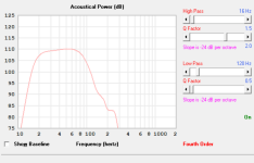
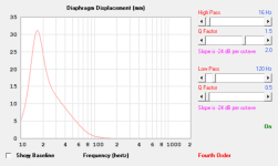
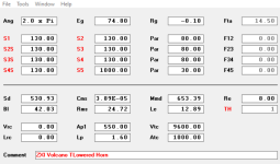
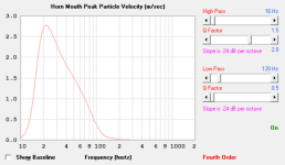

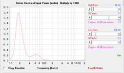
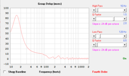
If the test boxes sound good. I could then really live with a pair of these in the front corners of the room with the tube driven racers fitted into false compartments in the front panel. Making it appear as though they are loading the cab and making all the bass!!
Will have to store the DJ subs on the houseboat if I go this way
Wanted to see how low can I tune this template with the ZXI 12". All that needs to be done is just scale the cab taller thus increasing pipe length and a lil bit of filter to graph this so, No idea how it would sound


If the test boxes sound good. I could then really live with a pair of these in the front corners of the room with the tube driven racers fitted into false compartments in the front panel. Making it appear as though they are loading the cab and making all the bass!!
Will have to store the DJ subs on the houseboat if I go this way
Attachments
The twin flared BR didn't get the right attention here. I have withdrawn the current BR concept and revisited the design in the original post in this thread with the intentions of pushing and prodding with what I have learned with the TL and TH models
Ok, every structure, brace and such changes the box segmenting somehow and tests in sims show that a lot of peaky dips in sims everywhere are from these
These heavy motored and stiff suspended drivers promise a lot of control and usually deliver, as seen with the Gothams and Fathoms as well as the original pioneer Sunfire, but they seem to demand stiffer volumes to present a very clean and detailed output. Again as proven by the pioneering examples
I combined the two points and redrew the box using the ND 1 model in Hornresp. This model seems to offer access to all controls in a non tapped model
So, a clean new Vb that doesn't stray away from the look of a BR and a clean new port that resembles a BR port and not a line. A new massaging of the twin flares and a touch of selective dampening such as a pool filter based leaky PR in the vent and results. There is too much straying from the topic here, and I want to present this development based on intuition cleanly, so expect part two. I feel better about conducting initial tests in a familiar BR environment, then moving onto the lines to compare
One grey area, what type of pipe model is best to represent a 100mm radius lip flare on a slot port? I have set Exp as a gamble for now
excited to see what happens when you get the dats 😃!
There’s no such thing as a 12” driver with a 700 gram moving mass and a 42 BL or the combo of 15 liter suspension stiffness. Even in the $1000+ category of car audio SPL drivers???
in so confused by all that craziness😝
There’s no such thing as a 12” driver with a 700 gram moving mass and a 42 BL or the combo of 15 liter suspension stiffness. Even in the $1000+ category of car audio SPL drivers???
in so confused by all that craziness😝
Thanks man, in my minds eye I see butterflied quarter sawn fronts, piano gloss black all over and brushed red alloy scoop. Gold 'Bassinga Volcano" badgeNICE model!
Bassinga as in Bass Singer, I have a loud and low singing voice
- Home
- Loudspeakers
- Subwoofers
- Flared BR ports with Hornresp?
