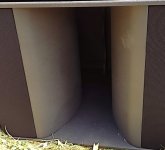
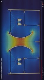
Yes, I did, see post 469 and 494, for example!have you thought about analyzing the rectangular bass reflex openings?
But I still want to continue my tests with rectangular ports, thanks for your examples!
In the past, i have made an experiment with a speaker in which I built 2 bass reflex openings, each tuned to the same frequency, 37hz. By covering one of them and positioning the speaker always with the opening down, I listened and measured in each individual case, but I found no obvious advantages for the port with nfr=0.5. It is true that both are generously sized, the straight port has 750 cm2 and the rounded one has a minimum section of 600 cm2, the box having an interior of approximately 200l, the speaker being 18tbx100.
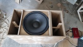
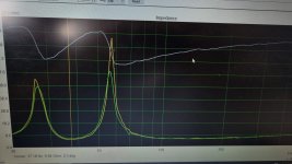
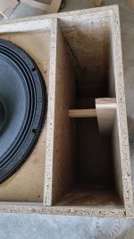
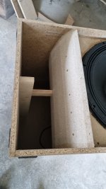


for very big port surfaces the advantage is probably not noticeable / measurable. the air verlocity and displacement is very low anyways and in addition the curvature of walls does not hugehly reduce the port cross section surface.but I found no obvious advantages for the port with nfr=0.5
the main advantages with flared ports would mostly be noticeable with smaller 2-way midwoofers.
thanks for sharing your experience!
some thoughts
one thing that kept puzzling me with all my tests, experiments and explanation attempts:
why would (apparently) nobody else discover the possibilities and advantages of a flared very narrow center section port?
the high air velocity of this central area seem to be mostly irrelevant and the losses to be mainly caused by transistion from "tube" (moving air) to "room"/"enclosure" (pressurized air). this is in contrast to most existing rules of thumb for ports.
I found three reasonable explanations and a fourth, more unpleasant one (for me at least):
1.
(the short one)maybe this technique and respective explanations exist already but I just did not find them yet. not entirelly sure about that, but there are indeed many industrial and DIY speakers with flared ports.
still, I did not find many with very small central sections. there is in fact a limiting factor with the proposed last port geometry (similar to @augerpro's augerport): the bigger the enclosure and the port diameter gets the less difference there is between a simple flanged port and an "optimized geometry port". also the central area can only be small for rather longer ports.
2.
(a simple one)the rules of thumb and traditional "vent loss" explanations were found decades ago when there were no low Vas / high excursion woofers at all. bass reflex loudspeaker drivers and enclosures were big and the resulting vent lenghts for sensible helmholtz resonances between 30 and 50 Hz were short. many "vents" were just round holes with the length equal to the enclosure material thickness. vents for big drivers need big diameters and if they are short they cannot have extended flanges or narrow central areas.
for big diameter ports the strouhal number is high anyways, so no big risk of turbulent flow separation at transistion from port to box volume and the room. also, with short ports there is no point in distinguishing the "central port area" from the port ends.
only rather recently (in terms of some decades) smaller high excursion woofers with very low VAS have been made and the necessary enclosure volumes decreased, requiring much longer ports for a low tuning frequency. using the known sensible Sd/port surface ratios and max. air velocities this leads to inpractical port lengths (occupying more space than the actual box volume) or unusable small port tube diameters.
the only solutions for such helmholtz resonator systems seem to be PRs.
3.
(my preferred one, even if I can only explain it in very simple words, as I am absoultely no expert in the complex aerodynamics/fluid flow field)in most papers and articles there are aerodynamic references to "fluid flow through circular tubes" and related concepts of laminar flow reynold number limit and flow/pressure development and related losses in tubes.
just for reference, here is an image from "aerodynamics for students", this is not related to bass reflex ports:
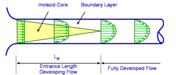
it shows the concept of fluid flow through a tube.
the medium is being pushed through the tube by pressure on the left tube entry side.
the boundary layer is occupying the whole tube surface after the entrance length. big velocity/pressure differences related to boundary layer are one (or the) main reason for turbulent flow. thick boundary layer leads to big turbulences.
there are three main and very substancial issues I have with the reference of helmholtz ports to fluid flow in tubes:
- the somewhat intuitive assumption that the driver pushes air out through the vent, similar to blowing air throuh a pipe (as shown above) is only true for frequencies substancially below helmholtz resonance, in the frequency range where driver and port output cancel eachother. I found this "intuitive assumption" even in quite scientific articles.
- the oscillating air flow in the resonator port is not induced by a static presssure from outside the port. the resonance does not need much energy from "outside" (or inside the box). The air in the port will even continue to oscillate (resonate) for a few cycles after the excitation has stopped. there is no "entrance lenght" and I suspect the boundary layer is very thin and may eventually even be "lubricated" by microscopic turbulence.
- at the peak output frequency (helmholtz frequency) the air flow in the port is COUNTERACTING the pressure in the enclosure. for an ideal lossles bass reflex speaker the force induced by the oscillating air in the port via the compliance of the box volume air would be so strong to counteract the driver diaphragm from moving at all. taking the image above as reference, the "inviscid core" would be inverted or rather fill the entire port.
[salvatti/devantier/button 2002][...] the Reynolds number can be much higher if the pipe has flared ends or smooth walls, [...] A practical upper limit for the Reynolds numer obtainable in loudspeaker ports is on the order of 100 000.
But still the laminar/turbulent flow principle, while perfectly reasonable for static fluid flow in a tube seems to be applied to the minimum diameter dimensioning and used as explanation for losses in ports.
It shouldn't!
(EDIT: here is a more scientific explanation of small boundary layer thickness by @andy19191!)
4.
(the embarassing one)I might simply be way off with my assumptions and someone might prove me wrong.
I hope this is not going to happen - but I encourage everyone to try it!
Last edited:
why would (apparently) nobody else discover the possibilities and advantages of a flared very narrow center section port?
What is the difference between a "flared very narrow center section" port and a conventional well designed port such as those shown on page 25 here? Note this is for 3-4 ways and so issues with port resonances will be largely absent unlike for 1-2 ways.
A port cannot be narrow if the oscillating slug of air is to displace sufficient air to match that of the woofer/s.
None, except that if you take a NFR (normalized flare rate)= 0.5 port (similar to the ones you pointed to) and use it for a small 4"-5" woofer with rather low displacement you end up with a very small central port section. The air speed in this section will get very high, but as far as I measured this is no problem.What is the difference between a "flared very narrow center section" port and a conventional well designed port such as those shown on page 25 here?
It can, but the air in the narrow section will have high speed. The only important thing here is to reduce the airspead by widening the port toward its ends.A port cannot be narrow if the oscillating slug of air is to displace sufficient air to match that of the woofer/s.
The advantage is that the small high acceleration part of the port can and will be short, thus the whole port can be smaller.
The conventional approach defines a minimum diameter/surface for (mostly) laminar flow. The point that it misses is that the critical section regarding turbulences is the port terminations, not the whole port. The center section flow will stay laminar even at high speeds.
Just for the sake of completeness let me add that the oscillating air quantity of a vent or PR will be considerably higher than the one displaced by the woofer. That's the whole point of vented or PR speakers.if the oscillating slug of air is to displace sufficient air to match that of the woofer/s.
Did I already mention before about that people need to be an expert in thermal/fluid dynamics before? 😉one thing that kept puzzling me with all my tests, experiments and explanation attempts:
why would (apparently) nobody else discover the possibilities and advantages of a flared very narrow center section port?
I don't want to come across grumpy, but some of your reasons summarize a bigger picture: that people/companies either don't care or are just simply not aware.
I think we can all agree on the fact that you quickly go into a big complex rabbit hole.
While in most practical cases just getting either a bigger port or just going for a different solution (PR or closed box with an additional woofer) is just a bit easier.
So at a certain point we can question ourselves how far we want to go into the rabbit hole?
Most importantly, how can we translate that to simple and elegant solutions?
Because keep in mind that a port that's way to long, basically needs to be cut in half to solve the problem.
Even with proper optimization I wonder that's even feasible?
And even if it is, we're still left with port resonances probably?
Don't be surprised that certain questions in the field are being left wide open.
I constantly bump into these.
In fact I have worked at companies where very smart people just simply couldn't grasp similar questions you're asking right now.
Which is also a compliment to all what you've done. 👍🏻
Personally, I am more interested in getting rid of the port resonances on a simple and elegant way.
Mostly because in my experience I find these far more limiting than optimizing port length and performance.
Some good working solutions have been proposed, unless I missed something, but I personally still find them practicality a bit cumbersome. I don't mean that on a offensive way at all.
Btw, I do think that your observations about high xmax low Vas drivers is a good one!
At the same time it's just part of the law of conservation of misery.
So after a while we just simply run into physical limits.
We can stretch it a little by optimizations, but even that won't help the extremes.
None, except that if you take a NFR (normalized flare rate)= 0.5 port (similar to the ones you pointed to) and use it for a small 4"-5" woofer with rather low displacement you end up with a very small central port section. The air speed in this section will get very high, but as far as I measured this is no problem.
Why will it be no problem? A high speed flow will separate rather than slow down if the flaring is anything other than gentle. Laminar flows are more prone to separating than turbulent flows due to their smaller shear stress. Flares/diffusers often have rough surfaces to encourage the slowly moving fluid next to the surface to mix with the faster moving fluid further out in order to remain attached for longer against the rising pressure slowing the flow down.
It can, but the air in the narrow section will have high speed. The only important thing here is to reduce the airspead by widening the port toward its ends.
The advantage is that the small high acceleration part of the port can and will be short, thus the whole port can be smaller.
One can accelerate/speed up the flow as aggressively as one likes and it will remain attached. The problem is decelerating/slowing which can only be done gently over a long length or else the flow will separate and the core flow continue moving in a straight line at the same speed.
The conventional approach defines a minimum diameter/surface for (mostly) laminar flow. The point that it misses is that the critical section regarding turbulences is the port terminations, not the whole port. The center section flow will stay laminar even at high speeds.
There seems to be some confusion here over the meaning of laminar and turbulent. The central flow will be turbulent if the Reynolds number is high enough but as the wall is approached the growing size of the velocity gradient will increase the size of the laminar shear stress until it is large enough for the flow to be laminar rather than turbulent. This is the laminar sublayer of a boundary layer which will always be present (except in one or two exceptional circumstances).
Laminar flow is undersirable if one is trying to diffuse/slow down a fluid with a gentle flare. Laminar flow can be unstable and the vortex streets being shed from the port are laminar at lower speeds. These laminar vortices will grow in size and the velocity become smaller over time as they disappear. If the flow is fast enough for it to become turbulent then these vortices will initially form as laminar ones with strong velocity gradients, grow in size until the laminar stresses become weak enough to be overcome by the intertia/Reynolds stresses at which point the motion will become more random/chaotic, the vortices will rollup and interact with each other and turbulence will be present.
Thank you very much for your input - I know my understanding of aerodynamics is probably way too intuitive.Why will it be no problem?
But by testing port geometries regarding compression, noise and harmonic distorsion I discovered that exceeding the rule of thumb air velocity limit of 10 m/s (I'll have to look up who stated this, but it was in the 70ies) in the center section of a port is no problem.
Edit:
I listed air velocity values in post #660, the maximum acceptable center air velocity for the tested flare port was above 22 m/s.
Provided the audible noise is caused by the flare, not the center section (which I am convinced of) I suspect that with a different driver/enclosure and a longer port the center air speed could be even higher.
But I'll have to test it.
Last edited:
Just for the sake of completeness let me add that the oscillating air quantity of a vent or PR will be considerably higher than the one displaced by the woofer. That's the whole point of vented or PR speakers.
The amount of sound generated depends on the amount of fluid displaced (i.e. surface area * normal velocity component). If a port is to produce a similar SPL to the woofer/s it will displace a similar amount of fluid.
If the port area is small the flow in the port will have to be raised to a high velocity to be squeezed through. This requires the kinetic energy of the fluid in the port to be raised to high level which will then be largely unrecovered when vented into the room. This largely lost energy comes from the driver via compressing the trapped air volume. The more the motion of the driver is opposed/resisted in order to get more energy from it the more it will move less and transfer less energy (force * velocity). This mechanism means a small/narrow port won't make much sound.
Thank you very much for your input - I know my understanding of aerodynamics is probably way too intuitive.
But by testing port geometries regarding compression, noise and harmonic distorsion I discovered that exceeding the rule of thumb air velocity limit of 10 m/s (I'll have to look up who stated this, but it was in the 70ies) in the center section of a port is no problem.
I would check your source. The rule of thumb I recall was 20-30 m/s. The figure to adopt of course depends on number factors.
PS This suggests something similar.
Last edited:
usually the port extends the response down an octave or so, thus the air quantity to be displaced by the port needs to be 4-fold of the woofer.If a port is to produce a similar SPL to the woofer/s it will displace a similar amount of fluid.
This is exactly what I mentioned in my posting yesterday night:This largely lost energy comes from the driver via compressing the trapped air volume.
It's a misconception to think the driver pushes air through the vent. On the contrary: the diaphragm and the port air are in phase at the helmholtz resonance.
The driver pushes air into the enclosure and the port air swings inside as well.
Yes. But again, this is only valid for frequencies way below helmholtz resonance where the driver moves and by doing this pushes air out through the port. Driver and port output are out of phase and cancel out (unloaded range, potentially dangerous for the driver).The more the motion of the driver is opposed/resisted in order to get more energy from it the more it will move less and transfer less energy (force * velocity).
Last edited:
I was talking in terms of energy in order to simplify. Whatever the frequency energy only comes from the driver (source). The kinetic energy in the port motion is large (so we can put aside other forms of energy) and it is largely unrecovered when vented into the room (sink). What's going on inbetween can to a fair extent be skipped if what we are interested in involves the source and sink. The same mass flow (i.e. same SPL) through a narrow port requires the kinetic energy to be raised a lot (proportional to square of velocity). Extracting work from a moving cone is achieved by opposing it's motion which will tend to reduce in response. So we won't get the same mass flow through a narrower port but less. The port will be quieter (and probably the driver). Assumes both ports are operating similarly w.r.t. to resonance (i.e. not comparing a port on resonance with one far from resonance).
By centre section do you mean the flow in the middle of the port or some form of physical cap placed at the end?
Provided the audible noise is caused by the flare, not the center section (which I am convinced of) I suspect that with a different driver/enclosure and a longer port the center air speed could be even higher.
By centre section do you mean the flow in the middle of the port or some form of physical cap placed at the end?
Thank you stv for this thread!
I quickly read through it recently and I'm more than happy to say without regrets that I don't use ports or BRs in my own designs (just unique diys) 😎
Port noises are practically skipped over by many, perhaps because universal simulators don't show problems. Port shape and position can make huge differences, and if one is making a ported 2-way speaker this can lead to audible problems easily.
Pure sine RTA at port tuning frequency is very revealing, I have done such tests too
I went through my REW nearfield measurements and collected port and woofer responses, normalized spl to 100Hz/100dB, used 200ms gating and 1/48 smoothing. Some measurements include xo and dsp-eq, some are without. All are straight tubes, many have flaring. Variance is huge!
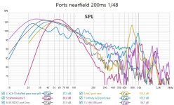
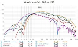
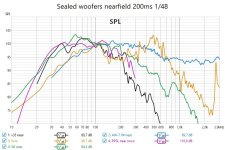


This is something most people don't even realize.position can make huge differences,
Although in a compact two way monitor there isn't that much wiggle room, for a bigger and taller system it's a very different story.
Just for fun experiment with Hornresp with an offset on the driver as well as the port (or even PR)
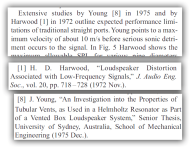
here is the excerpt from the salvatti, devantier, button paper referring to the 10 m/s value:I would check your source. The rule of thumb I recall was 20-30 m/s.
I mean the middle section of the port that is narrow.By centre section do you mean the flow in the middle of the port or some form of physical cap placed at the end?
I just remembered that I did a test regarding losses due to boundary layer at port surface, see post #498.
I made two test ports with identical "throat" and "mouth" cross section surfaces.
One is round, thus has the least port wall boundary layer contact surface (middle area with 20 mm diameter; port called "small 3d printed port").
The other one is rectangular with a very thin and wide cross section (6*53 mm in the middle area), thus very big boundary layer contact surface ("flat port with flanged height").
considering the "fluid flow through a pipe" concept and the potential losses at the port wall surfaces the round port would clearly be much less lossy than the wide rectangular port. But in fact it's even the other way around!
this seems to confirm the very thin boundary layer and related losses.
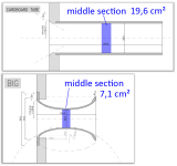
(please note that the tube port had a small roundover at the interior end as well, but it's not shown here in the plan)
here are the results in the adapted table, now with middle section air velocities and compression:

and, to better relate the compression to middle section air velocities, a coparison graph showing compression vs. middle section air velocity:
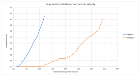
while the increased air velocity is of course related to compression, there is no direct relation for the middle section air velocities of tube port and flange port.
the flanged port does not compress up to middle air velocities of 11 m/s, the tube port starts compressing at 3,7 m/s middle section air velocity.
It seems obvious to me that the compression is NOT related directly to the middle section airspeed, otherwise the two graphs would be near eachother.
instead it is mostly dependent on the transistion between velocity air movement to air pressurization. that is: at the port terminations.
of course it will most likely still be relevant to keep the middle section air velocities low, but the main focus of port development should remain at the terminations.
I made two test ports with identical "throat" and "mouth" cross section surfaces.
One is round, thus has the least port wall boundary layer contact surface (middle area with 20 mm diameter; port called "small 3d printed port").
The other one is rectangular with a very thin and wide cross section (6*53 mm in the middle area), thus very big boundary layer contact surface ("flat port with flanged height").
considering the "fluid flow through a pipe" concept and the potential losses at the port wall surfaces the round port would clearly be much less lossy than the wide rectangular port. But in fact it's even the other way around!
this seems to confirm the very thin boundary layer and related losses.
I added information to my table as posted here (#660), showing the behaviour of a straight tube and a optimized flared port with raising input voltages (1 dB steps). the flared port has a much smaller middle section cross section surface:So we won't get the same mass flow through a narrower port but less.

(please note that the tube port had a small roundover at the interior end as well, but it's not shown here in the plan)
here are the results in the adapted table, now with middle section air velocities and compression:

and, to better relate the compression to middle section air velocities, a coparison graph showing compression vs. middle section air velocity:

while the increased air velocity is of course related to compression, there is no direct relation for the middle section air velocities of tube port and flange port.
the flanged port does not compress up to middle air velocities of 11 m/s, the tube port starts compressing at 3,7 m/s middle section air velocity.
It seems obvious to me that the compression is NOT related directly to the middle section airspeed, otherwise the two graphs would be near eachother.
instead it is mostly dependent on the transistion between velocity air movement to air pressurization. that is: at the port terminations.
of course it will most likely still be relevant to keep the middle section air velocities low, but the main focus of port development should remain at the terminations.
Last edited:
- Home
- Loudspeakers
- Multi-Way
- Investigating port resonance absorbers and port geometries
