Have test equipment to do tests. I hope to be in the ball park before testing.
I have the test equipment I need. As I don't have a big parts bin I had hoped to get in the ball park before testing.
Over a year ago a designer offered to give our Men's Shed a design to build - a year it has never materialized so I offered to come up with something hence I have a 20-0-20 toroidal. What I've learned is I'm not the right volunteer for this project. I will plod on in my own time for my own learning nevertheless.
Many thanks for your time and input, I've learned some stuff for sure.
Cheers
I tested that many permutations I couldn't post them all, I only posted one. - Qspice tells me 320mA for that one.What exactly you've meant with “ 320ma to base “? Resistors in this circuit would not allow such current to appear in base - emitter junction, 36,5k resistor allows just 0,74ma base current.
I have the test equipment I need. As I don't have a big parts bin I had hoped to get in the ball park before testing.
Over a year ago a designer offered to give our Men's Shed a design to build - a year it has never materialized so I offered to come up with something hence I have a 20-0-20 toroidal. What I've learned is I'm not the right volunteer for this project. I will plod on in my own time for my own learning nevertheless.
Many thanks for your time and input, I've learned some stuff for sure.
Cheers
You can increase parts count slightly and overcome current existing design limitations. Small power transistors are not so pricey, so better would be to add some vas stage and enjoy allmost full +-28v swing at output i think.
Too much screen time, not enough sleep makes silly typos - micro-amps DUH!Qspice tells me 320mA for that one
Other: only I will bi-amp so bought a bigger transformer. The other guys will use a 15 or 18 W one with regulation to the op-amp.
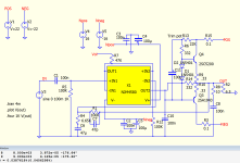
The inspiration comes from Rod Elliot https://sound-au.com/project76.htm
Thanks for that suggestion. I have found a UK importer/distributor (not from E-bay) who'll post 2sc5200/2sa1943 in small lots for a reasonable charge. In the simu, without drivers, I now get 560mV to the base of the 2sc5200 with a quiescent current of 50mA. The total resistance across both Re equals 33mV. With a +15/-15 transformer and regulation to 15V for the op-amp this looks like something worth the effort to build and test, I dare to say.Do you have another complementary power transistors in simulator library? Like 2sc5200/2sa1943 , bd138/bd139 etc?
Thanks for your help with this project.
Attachments
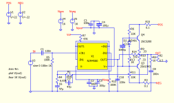
Can i comment again? 22k in this schematic is too high value, if no drivers used. Positive halfwave will clip early, because of asymmetry in driving currents. While keeping simplicity, i see only one solution - add big capacitor,like 1000uf+, between output transistor bases. This will route opamp output current to positive side too, while keeping it biased at same time. Otherwise, driver transistors needed.
Cheers, I can see the difference with 1000u cap when running the simu.add big capacitor,like 1000uf
I'll also try it with drivers. I appreciate your tips for my project.
Also, i see you trying to do bootstrap, with 100uf capacitor. One note - when cap is connected at midpoint of two resistors, they should be similar values for best result. Also you may add diode , in series with resistor, which one goes to positive supply, to prevent capacitor discharge to power supply.
Good point - I had just copied this from the example on Rod Elliot's website. I'm better with 22K on each rail. Next weekend I'll try with drivers in the Spice simu. Thanks for explaining these points, I learn a lot.Also, i see you trying to do bootstrap, with 100uf capacitor.
When I simulate with UF300x diodes I can use 11k resistors - useful. DigiKey lists these as obsolete, I'll try to find a replacement part. Cheers!
Attachments
R11, R12 not needed. C10 connection looks strange. Without it opamp oscillates? Such capacity should not be connected to ground. Better place small cap between -in2 and out2 pins.
Caps in series or by-pass caps - film caps abt10nF or uF? I'm curious to learn what the benefit is.place small cap between -in2 and out2 pins.
R. Elliot suggest C10 from 10 to 100n to avoid oscillation but simu is fine without. Many thanks, again.
C10 is placed from opamp output to ground, and if you read datasheets of most of opamps, some specifies maximum load in picofarads for stable operation. Actually you loading output at high frequencies, this may increase distortion. Better provide local feedback, by small capacitor , begin with 5pf and increase until oscillation stops. When output stage is slow, opamp waits for signal at feedback , and increases output very fast as it can, until response is received. If small cap added, opamp gets response from own faster output and don't increase output too fast. But this method will increase distortion at high frequencies too, so don't put bigger than needed cap - it's compromise solution.
Thanks, I'll trial that when bread-boarded. C10 is redundant for this op-amp with its 5V/µs slew rate. Small cap between -in2 and out2 pins I guess can be 470p and I'll trial that too when bread-boarded.Better provide local feedback, by small capacitor , begin with 5pf and increase until oscillation stops. When output stage is slow, opamp waits for signal at feedback , and increases output very fast as it can, until response is received.
Learning and correcting using earlier tips, I've got 562mV at Q1 base/emitter with Re much lower at 4.22K. Going back to my very first question abt Re values, I have learned that 4K is a good starting point for a circuit using op-amp for the driver and up 10K when two diodes are used. The quiescent current is acceptable at 50mA.
Attachments
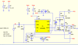
Maybe i will repeat, but R6 will affect not only idle current, but maximum output current too. Try simulating a low frequency, like 20hz, at full output swing, with variuos c11 values. If this capacitor will be too small , output current at clipping point, positive halfwave, will depend on R6 too. Smaller resistor - more amperes possible. With high capacity capacitor, it will hold bias voltage , and allow opamp current to pass q1 base, allowing q1 to just amplify opamp current. 470pf for local feedback is way too much i think, try 5-10 pf at first test, also limit power supply with small power resistors like 10 ohms 0,25W , no speaker. Resistors will heat up or burn, if something goes wrong, like oscillation.
Previous schematic was a little better i think, you could split this resistor to two , each 2-2,2 kilohms, and put bootstrap capacitor from midpoint to output. During positive halfwave, current will be less dependent on output amplitude. Without bootstrap, if base- collector voltage is low, current through R6 will be low too, and bias decrease, also max current too. Earlier clipping of positive halfwave.
And again, seems you wanna use lower supply voltage for opamps than for output transistors, thats will not improve output. Try to reduce your +-22 voltage in simulator to lets say +-16 volts , outputting full swing to load, and you shoul see no difference,or very small. In practice with this circuit , as there are no voltage amplification stages, only voltage drops occurs, and you need bigger heatsink. Or try another opamp, with higher available supply voltage, then you can increase output at same supply voltage, making circuit more effective.
Thanks for this helping me.470pf for local feedback is way too much i think,
I'm don't know what you are referring to, I don't see a value like that
Work in progress..split this resistor to two , each 2-2,2 kilohms, and put bootstrap capacitor from midpoint to output.
Last edited:
With opamp local feedback i mean additional capacitor ,between output opamp output and inverting pins . Earlier you had 0,1uf to gnd from that opamp output in schematic ,but that was not a correct way to supress oscillation.
Bootstrap is a little different in class-d amplifiers and switch mode converters/power supplies , it has diode and capacitor only, maybe this confuses you .
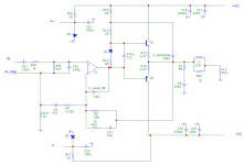
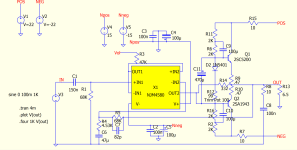
With attached picture i will try to explain what i mean with bootstrap and local feedback .You can include a diode in series with R14 from my picture ,anode to power supply +.
Also ,don't use same ground for input and power ,or speaker output gnd .Inductor also better to have ,keeps feedback stable at high frequencies ,especially if longer wires to speaker .I think only active speakers with very short wires can work ok without this inductor.
Input filter also better to have .It keeps away RF noises from input , sometimes input cables are badly shielded ,and can receive noise from mobile phone ,placed near .
Add a wire from input jack ground ,if you will not use volume control potentiometer at input, or from "int_gnd" to power supply capacitors point ,where they are joined together .Resistor 10 ohms included to prevent ground loop. Only in mono variant ,when only one channel exists ,no problems with ground loop.
Also probably speaker output ground needs to be connected to this ground ,no at amplifier pcb gnd. There are topics discussing where to connect speakers gnd better ,but i don't have direct link .Also , you had capacitor 68p from amplifier output to opamp inverting input ,directly . If you plan to make pcb ,include resistor in series .Such capacitor in other schematics is smaller capacity , like 10pf . At audio frequencies 68pf there may have impact no only on frequency responce , but at distortion and stability too , so be careful .Voltage regulators for opamp is sometimes good idea ,sometimes not . In case of opamp output overload ,regulator would not limit current ,and if opamp can't properly limit output current ,ir may fail .I have included zeners and resistors ,they would kinda protect opamp ,as supply voltage will reduce and zener stop conducting ,just need to choose proper resistance .Supply voltage rejection is already high on opamps ,probably you will have no hum with just zener and resistor .In my design i use just zeners and resistors ,capacitors 100u to gnd, from opamp supply pins to gnd ,and there's no audible hum.
Bootstrap is a little different in class-d amplifiers and switch mode converters/power supplies , it has diode and capacitor only, maybe this confuses you .
With attached picture i will try to explain what i mean with bootstrap and local feedback .You can include a diode in series with R14 from my picture ,anode to power supply +.
Also ,don't use same ground for input and power ,or speaker output gnd .Inductor also better to have ,keeps feedback stable at high frequencies ,especially if longer wires to speaker .I think only active speakers with very short wires can work ok without this inductor.
Input filter also better to have .It keeps away RF noises from input , sometimes input cables are badly shielded ,and can receive noise from mobile phone ,placed near .
Add a wire from input jack ground ,if you will not use volume control potentiometer at input, or from "int_gnd" to power supply capacitors point ,where they are joined together .Resistor 10 ohms included to prevent ground loop. Only in mono variant ,when only one channel exists ,no problems with ground loop.
Also probably speaker output ground needs to be connected to this ground ,no at amplifier pcb gnd. There are topics discussing where to connect speakers gnd better ,but i don't have direct link .Also , you had capacitor 68p from amplifier output to opamp inverting input ,directly . If you plan to make pcb ,include resistor in series .Such capacitor in other schematics is smaller capacity , like 10pf . At audio frequencies 68pf there may have impact no only on frequency responce , but at distortion and stability too , so be careful .Voltage regulators for opamp is sometimes good idea ,sometimes not . In case of opamp output overload ,regulator would not limit current ,and if opamp can't properly limit output current ,ir may fail .I have included zeners and resistors ,they would kinda protect opamp ,as supply voltage will reduce and zener stop conducting ,just need to choose proper resistance .Supply voltage rejection is already high on opamps ,probably you will have no hum with just zener and resistor .In my design i use just zeners and resistors ,capacitors 100u to gnd, from opamp supply pins to gnd ,and there's no audible hum.
Attachments

I tried this and it works with bootstrap on both rails only, so far.2-2,2 kilohms, and put bootstrap capacitor from midpoint to output
Other: 18v trans are readily available and affordable plus 15W reg. for op-amp. We hope to use this option.
Attachments
Thanks,With opamp local feedback i mean additional capacitor ,between output opamp output and inverting pins . Earlier you had 0,1uf to gnd from that opamp output in schematic ,but that was not a correct way to supress oscillation.
Bootstrap is a little different in class-d amplifiers and switch mode converters/power supplies , it has diode and capacitor only, maybe this confuses you .
With attached picture i will try to explain what i mean with bootstrap and local feedback .You can include a diode in series with R14 from my picture ,anode to power supply +.
Also ,don't use same ground for input and power ,or speaker output gnd .Inductor also better to have ,keeps feedback stable at high frequencies ,especially if longer wires to speaker .I think only active speakers with very short wires can work ok without this inductor.
Input filter also better to have .It keeps away RF noises from input , sometimes input cables are badly shielded ,and can receive noise from mobile phone ,placed near .
Add a wire from input jack ground ,if you will not use volume control potentiometer at input, or from "int_gnd" to power supply capacitors point ,where they are joined together .Resistor 10 ohms included to prevent ground loop. Only in mono variant ,when only one channel exists ,no problems with ground loop.
Also probably speaker output ground needs to be connected to this ground ,no at amplifier pcb gnd. There are topics discussing where to connect speakers gnd better ,but i don't have direct link .Also , you had capacitor 68p from amplifier output to opamp inverting input ,directly . If you plan to make pcb ,include resistor in series .Such capacitor in other schematics is smaller capacity , like 10pf . At audio frequencies 68pf there may have impact no only on frequency responce , but at distortion and stability too , so be careful .Voltage regulators for opamp is sometimes good idea ,sometimes not . In case of opamp output overload ,regulator would not limit current ,and if opamp can't properly limit output current ,ir may fail .I have included zeners and resistors ,they would kinda protect opamp ,as supply voltage will reduce and zener stop conducting ,just need to choose proper resistance .Supply voltage rejection is already high on opamps ,probably you will have no hum with just zener and resistor .In my design i use just zeners and resistors ,capacitors 100u to gnd, from opamp supply pins to gnd ,and there's no audible hum.
I need to read this carefully and make sure I understand it all. Many thanks.
I did change the input and feedback values to reduce the output to -1.0mV .
Cheers
Actual dc value at output will be minimal, if input to gnd resistor and feedback resistor are equal values. Then opamps input disbalanse millivolts will be actual, and you can ignore that - values up to 100 mV i think will not hurt any speaker, just can make some poping sound while turning on and off power .
- Home
- Amplifiers
- Solid State
- Biasing target for push-pull amp