Hello Hornresp modellers
When it comes to port flares, can this be modelled using HR? I have set the flare rate just for illustration purpose. In HR a segment can be set as conical, parabolic and such. Which one is most suitable for the slot port segment? Is it still conical if the port is rectangular and flare rate is like an angled board with a lip radius?
I would like to learn how to correctly enter the data for a box like this to build a Hornresp model. I think I can do the two parts of the port ok and assume the radius will be ignored by the port frequencies and just there for looks and flow. Interested in learning to correctly model such angled flare on just the exit section and both sections
Is the driver volume done as a segment too? Really struggling to understand the workflow in this situation
The illustration is similar to what I want to model acoustically. I would build such a cab with plywood outers and use CNC'ed MDF for the ports and fillets
Can Hornresp model this better, or is this best done as a BR in WinISD and somehow using the port flare function?


This will be edge treatment under assumption that these radii are invisible to the bass frequencies and for structural and aesthetic reasons

When it comes to port flares, can this be modelled using HR? I have set the flare rate just for illustration purpose. In HR a segment can be set as conical, parabolic and such. Which one is most suitable for the slot port segment? Is it still conical if the port is rectangular and flare rate is like an angled board with a lip radius?
I would like to learn how to correctly enter the data for a box like this to build a Hornresp model. I think I can do the two parts of the port ok and assume the radius will be ignored by the port frequencies and just there for looks and flow. Interested in learning to correctly model such angled flare on just the exit section and both sections
Is the driver volume done as a segment too? Really struggling to understand the workflow in this situation
The illustration is similar to what I want to model acoustically. I would build such a cab with plywood outers and use CNC'ed MDF for the ports and fillets
Can Hornresp model this better, or is this best done as a BR in WinISD and somehow using the port flare function?
This will be edge treatment under assumption that these radii are invisible to the bass frequencies and for structural and aesthetic reasons
Not sure if it is something I am interested in, I merely make a note of the air speed in the port, if it is a design restriction that causes too high velocity then Aero ports will be the thing to choose.
I am guessing that learning to model twin flares would apply to a round or oval cross-section too, straight or elbowed when the port is too long. The query and interest would be the same, modelling twin flaresif it is a design restriction that causes too high velocity then Aero ports will be the thing to choose.
In another thread, Art mentioned the use of twin flares to attain a lower tuning. It would be good to be able to start modelling with the conical taper and progress to more a more curved profile to the flare using the different segment settings like con, par and exp in HR
This is my 10" sub box now with a 43Hz port and 20L driver volume. I want to try to angle the boards first to see if Fb can be dropped to 33Hz. And then try to curve that all the way to the bend to see those results too. If I tune that to 33Hz as is, the port becomes too long to fit the box
Learning how to input data into HR for a segmented and tapered reflex port will also help me reduce that driver volume to a suitable compression chamber and fold a back loaded horn from that chamber to model an actual scoop for my 12" sub after completing this 10" one
I watched the very well done tutorial vids on @LORDSANSUI's site, and I am guessing I would need to create a system model in HR as shown in the HR related vid. Just totally lost with finding the workflow to enter the data to create this system model of a driver chamber and tapered port segments
Learning how to input data into HR for a segmented and tapered reflex port
Hello Randy,
The CH2 model in Hornresp was create just to simulate what you want to do.
Check the post #13442 and attachment following the next posts.
https://www.diyaudio.com/community/threads/hornresp.119854/page-673

Is it still conical if the port is rectangular and flare rate is like an angled board with a lip radius?
Greets!
If there are any parallel walls it's parabolic regardless of design.
Thanks for the tip. I am trying to explore the menus and windows in HR to access this model but not quite understanding what to do with itHello Randy,
The CH2 model in Hornresp was create just to simulate what you want to do.
Check the post #13442 and attachment following the next posts.
https://www.diyaudio.com/community/threads/hornresp.119854/page-673
I really cant make any headway on how to start entering this model. Is it just using the first segment for driver volume and second segment for port section 1 and third segment for port section 2 to make a weird looking TL? Totally lost on how to start
Totally lost on how to start
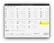
Start from the begining, so try to set hornresp to use CH3. There are two ways of doing it, the easiest one is is by double clicking over the model until you find CH3.
The 2nd step is about the inputs, in the link I shared there is a PDF file where you can find some some sketches, system models, etc, in the website there are more, so, try to match the name of the box (segment) in the system model with the name indicated over the Loudspeaker sketch. Each geometry of the loudspeaker will be represented by a different box in the system model. It's like LEGO, you need to connected pieces.
In your case, you may not need the H1 and H2 segments so you can set them to 0.
In the manifold box I set the H3 segment to 0, check that hornresp input data.
Attachments
There is other way of modeling your loundspeaker,
Check the VBSLOT3 in the website. The trick part is that we use the system model ND, but it's inverted.
https://freeloudspeakerplan.rf.gd
Check the VBSLOT3 in the website. The trick part is that we use the system model ND, but it's inverted.
https://freeloudspeakerplan.rf.gd
I’m gazing upon a sheer cliff with how I am finding this learning curve. Not really getting anywhere by studying the examples, as even more confused now with the driver volume being called all sorts of things in the system models
Take the VBSLOT3. This is a driver volume and flared ports, much like what I am trying to model
The driver volume is called TC in the drawing and system model, but I somehow I can't find how to create/set/edit such a driver volume so that HR can show me my 20L as the green TC system model component. Does TC mean throat chamber? So a driver volume is called the throat chamber? Then what is the TA in the system model and TP in the drawing in yellow? Why are they labelled differently like this? The only thing that I can understand is the H!-H4 being pipe segments
What is the purpose of TC, TA and TP in the system model? But then any understanding gets blown out of the water when I look at VBSLOT2

Here, the driver volume is called RC? Why is this not done with the same system model component for the driver volume? Why not TC again?
I have worked out how to set this string using the first segment for driver volume and the next two segments as the two parts of the port

But totally lost on how to add the green TC and yellow TA/TP components instead of the H1 above in the same way as in the VBSLOT3 model

I can see how this makes me look a bit slow, but yeah, really struggling to make head's and tails of this
Take the VBSLOT3. This is a driver volume and flared ports, much like what I am trying to model
The driver volume is called TC in the drawing and system model, but I somehow I can't find how to create/set/edit such a driver volume so that HR can show me my 20L as the green TC system model component. Does TC mean throat chamber? So a driver volume is called the throat chamber? Then what is the TA in the system model and TP in the drawing in yellow? Why are they labelled differently like this? The only thing that I can understand is the H!-H4 being pipe segments
What is the purpose of TC, TA and TP in the system model? But then any understanding gets blown out of the water when I look at VBSLOT2
Here, the driver volume is called RC? Why is this not done with the same system model component for the driver volume? Why not TC again?
I have worked out how to set this string using the first segment for driver volume and the next two segments as the two parts of the port
But totally lost on how to add the green TC and yellow TA/TP components instead of the H1 above in the same way as in the VBSLOT3 model
I can see how this makes me look a bit slow, but yeah, really struggling to make head's and tails of this
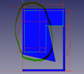
How does Hornresp see this cab? Is the breakdown in the pic valid?

1 - this column of air is the driver volume? 172mm x 340mm base and 330mm height
2- this tapered column is the first port segment? 120mm x 340mm fat end opening and 60mm x 340mm thin end. How does Hornresp see its length? Is that the full height, including the top and bottom green blocks?
3 - this tapered column is the second port segment? 120mm x 340mm on the exit and 60mm x 340mm at the elbow

Those two green blocks at the intersections. How does Hornresp deal with those?
Is it valid to set this as a 3 segment TL like so? I have set port lengths at full length of the longer wall and set the driver volume as parabolic and ports as conical. Please bear in mind that this is just for illustration and learning so I may correctly go on to adjust things until I get close to the desired response
@David McBean and the Hornresp gurus

1 - this column of air is the driver volume? 172mm x 340mm base and 330mm height
2- this tapered column is the first port segment? 120mm x 340mm fat end opening and 60mm x 340mm thin end. How does Hornresp see its length? Is that the full height, including the top and bottom green blocks?
3 - this tapered column is the second port segment? 120mm x 340mm on the exit and 60mm x 340mm at the elbow
Those two green blocks at the intersections. How does Hornresp deal with those?
Is it valid to set this as a 3 segment TL like so? I have set port lengths at full length of the longer wall and set the driver volume as parabolic and ports as conical. Please bear in mind that this is just for illustration and learning so I may correctly go on to adjust things until I get close to the desired response
@David McBean and the Hornresp gurus
Attachments
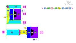
The trick part is that we use the system model ND, but it's inverted
As I mention, this model is inverted, so TC (Thorat Chamber) in general, is the volume of the chamber in front of the driver while RC (Rear chamber) if the volume of the chamber in the back of the driver.
Attention that the volume refer to the chamber, not to the driver.
Take the attached image as an example.
TC = The volume of blue space
RC = Volume of the purple space
If you want to improve further the precision you can also consider:
TC = The volume of blue space + volume of the air inside driver's cone
RC = Volume of the purple space - volume of the driver
The segments are the volumes of the spaces between the chambers and the air outside the loudspeakers. The geometry is very important for them, so for
the segments you need to specify how the volumes changes according to the length. For a while, assume that they are Parabolic flare, so set them to be PAR. You will understand in the future.
H1 is the first segment, for ND model it connects TC to H2,
H2 segment connects H2 to H3
H3 segment connects H2 to H4
H4 segment connects H3 to the output
The system model with the lines will indicate how those boxes are connected and arranged. What are the paths where the air can move.
For Nd model you have up to 4 segments to use, but if you model is simply, you can use only one, is up to the user to define the amount of segments to use.
For your model, you need at leas 2 segments in order to consider those areas variations due to negative and positive flare you want to implement in the vent.
Each segment to be specified requires 4 inputs:
1) Area of the throat (entrance)
2) Area of the mouth (exit)
3) Lenght
4) Flare (assume PAR)
Note: Your green areas needs to be incorporated in the segments.
Attachments
@LORDSANSUI
Hey man thanks for taking the time and effort to educate. I am very grateful
I can follow the layout that you are explaining but still lost with how to add components other than the segments, Like the RC, TC and TA components
I think this is the only part that I sort of understand how and where to enter and edit. For my model, I can't seem to work out which menu/feature to use to create the RC, and TA if needed
Am I understanding correctly that if I reverse the driver so that the magnet is in free air, the drivers working volume would be TC instead of RC?
Many thanks again for trying to help me learn
Hey man thanks for taking the time and effort to educate. I am very grateful
I can follow the layout that you are explaining but still lost with how to add components other than the segments, Like the RC, TC and TA components
For your model, you need at leas 2 segments in order to consider those areas variations due to negative and positive flare you want to implement in the vent.
Each segment to be specified requires 4 inputs:
1) Area of the throat (entrance)
2) Area of the mouth (exit)
3) Lenght
4) Flare (assume PAR)
Note: Your green areas needs to be incorporated in the segments.
I think this is the only part that I sort of understand how and where to enter and edit. For my model, I can't seem to work out which menu/feature to use to create the RC, and TA if needed
Am I understanding correctly that if I reverse the driver so that the magnet is in free air, the drivers working volume would be TC instead of RC?
Many thanks again for trying to help me learn
You are very close to understand. Try to mouse over the texts and fields inside hornresp.
Many input, if you double click the text will check the function of the field.
In the website you reverse engineering the simple models ans slowly move to the more complex ones 🙂
Many input, if you double click the text will check the function of the field.
In the website you reverse engineering the simple models ans slowly move to the more complex ones 🙂
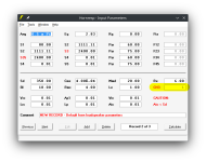
Is this about right? Does my model need a TA too? I am guessing that it does not


I hope this is done correctly. I changed the segment area and length until I had 34Hz Fb. It seems that increasing flare to my original board angles gives a higher Fb around 60hz
If I have learned to do the two part port with angled boards correctly, I would like to try using non-tapered segments but with a radius at the entry and exit. I think HR allows for this, but I can't seem to locate where and how to set this
A bass reflex cabinet does not have a throat in front of the driver, so does not need a throat adapter (TA).s this about right? Does my model need a TA too? I am guessing that it does not
In alphabetical order (as of https://www.diyaudio.com/community/threads/hornresp.119854/page-542#post-6234405):
AC = Absorber Chamber (light blue)
AP = Absorber Chamber Port (yellow)
D = Driver (light red)
H1 to H4 = Horn Segments 1 to 4 (light blue)
PR = Passive Radiator (light brown)
PT = Offset Port Tube (yellow)
RC = Rear Chamber (light green)
RP = Rear Chamber Port (yellow)
S = Stub (yellow)
TA = Throat Adaptor (yellow)
TC = Throat Chamber (light green)
TP = Throat Chamber Port (yellow)
The band pass system codes remain the same as before:
C1 to C3 = Chambers 1 to 3 (light green)
D = Driver (light red)
PR = Passive Radiator (light brown)
P1 to P3 = Ports 1 to 3 (yellow)
Thanks for porting the info Art. That HR thread is formidable in content and size!
GM
This is what I have observed while trying to model with these high power, high excursion and low Vas DS18 drivers. Since these are being used for 'subwoofers' to work in the sub 100Hz band. The driver volume and port just cant help but fall in that zone aspect wise where it becomes a linked set of segments rather than a main volume exciting a smaller port volume as in old school style BR. Folding cant be avoided either if keeping decent cross sections
This is why I have turned to HR, to see if those large port segments can be manipulated to an advantage. I do think this is a necessary direction to explore with these drivers if vented systems are to be moddelled effectivaly
Now I have no idea if I am modeling in HR correctly now. Will wait for confirmation on this to proceed with confidence
Using the ZXI12.4D. This is a 16kg driver! The retail box looks more than the modeled 20L Vtc/Vb and its going to be more of a case of all ports! For a gross system volume around 30-50L depending on port type and tuning. This is acceptable system volume, so can the ports be messed with?
Yes they can
Angling the boards to twin opposed flares models degenerated response over parallel sided running the cross-section at the elbow full length so a fail
Running an angled board at the exit with a shorter of the two segments is effective if the longer segment is parallel and same as the x-area of the elbow, if that longer segment length is increased
Running both segments with parallel sides and same x-area as the elbow is the most effective and resembles the WinISD model for BR. I am guessing that the potential to sound like a poor aspect BR is there if it can 'tuba'
Running a longer and larger tapered port where the entry is 80cm2 and exit is 500cm2 and as well increasing the Vtc/Vb to 30L is also very effective and on the larger 50L side
Getting rid of the driver volume as such and just modelling a narrowing taper TL is very effective with the flattest response that also reaches the lowest
Turning that TL into a widening taper is also very effective, if the TL length is increased
Again GM
If I am reading your presented thoughts from this ported quote correctly, you deduce that such drivers are best built with pipe systems like the last three examples and prefer the sound of the first and last of those last three examples
Can I correctly say that the first of the last three is a scoop type BLH and the last is a proper BLH?
That if I invert the driver due to clearance issues, they become tapped horns? If I keep it simple and use the Nd models for the last three, its a tapped horn due to Vb being cone side?
That I should look at those two BLH models towards sound reinforcement and the middle narrowing TL model as 'monitor' grade
Am I learning yet man?
To model my speaker, I found that @LORDSANSUI's advice to use the Nd model in a similar manner to the VBSLOT3 design allowed me to create the two port segments. Since this uses inverted driver, the driver volume is now coded as TC So how anal is HR about such coding? The question is unanswered if such a model needs that interfaceA bass reflex cabinet does not have a throat in front of the driver, so does not need a throat adapter (TA).
Greets!
Been designing tower/column designs since the mid '60s and empirically learned that it's not a strong enough 1/4 WL resonator until it tunes a reflex/BR's alignment lower, i.e. need to shorten the vent to match it, which can sound a bit better damped, like when 'critically damping' the vent to remove any obvious 'ringing', but a true [constant taper] MLTL [by my definition] adds some obvious driver control like when a larger/longer vent is used on a BR except without the strong vent harmonics comb filtering with the driver's output [think Jensen Ultraflex/Onken 360].
In short, trading an oversize vent on a BR damped to 'taste' for a somewhat larger high aspect ratio cab with less damping + large, short vent for a net increase in efficiency/lower distortion, so by my definition many of the designs posted aren't MLTLs, but extended bass shelf alignments [EBS] in a high aspect ratio cab.
For instance, many of the MLTLs are 40-42" high after MJK's designs and once damped, quite smooth/extended, but IME it takes closer to 60" with Vas or larger net Vb to get the sort of damping/'heart attack fast' transient [horn like] response I prefer.
Many drivers today have extremely stiff suspensions [low Vas] that combined with a low Fs tuning, high power handling [Xmax] requires TL size/length vents to have a low vent mach, so better overall to morph this combo into an inverse tapered [ML] TQWT with 10:1 CR proving a good place to start simming and more often than not 'close enough', then fine tune with a vent 'stub' or learn compression horn theory if you want the best trade-off of size Vs gain BW.
Re the Tabaq, I've only looked at the original? with a really low tuning below Fs, so strictly a nearfield alignment IME and too high an aspect ratio, i.e. not enough cross sectional area [CSA] for its path-length to suit me, so based on what you've said, need to either increase it and/or add more damping to smooth it out........... or not as some of the sims I've seen look like a Rocky Mountain profile, yet folks claim a great performer, so just more proof that B0$3 was right, folks in general like their sound really 'rich' [audible harmonic distortion].
GM
GM
This is what I have observed while trying to model with these high power, high excursion and low Vas DS18 drivers. Since these are being used for 'subwoofers' to work in the sub 100Hz band. The driver volume and port just cant help but fall in that zone aspect wise where it becomes a linked set of segments rather than a main volume exciting a smaller port volume as in old school style BR. Folding cant be avoided either if keeping decent cross sections
This is why I have turned to HR, to see if those large port segments can be manipulated to an advantage. I do think this is a necessary direction to explore with these drivers if vented systems are to be moddelled effectivaly
Now I have no idea if I am modeling in HR correctly now. Will wait for confirmation on this to proceed with confidence
Using the ZXI12.4D. This is a 16kg driver! The retail box looks more than the modeled 20L Vtc/Vb and its going to be more of a case of all ports! For a gross system volume around 30-50L depending on port type and tuning. This is acceptable system volume, so can the ports be messed with?
Yes they can
Angling the boards to twin opposed flares models degenerated response over parallel sided running the cross-section at the elbow full length so a fail
Running an angled board at the exit with a shorter of the two segments is effective if the longer segment is parallel and same as the x-area of the elbow, if that longer segment length is increased
Running both segments with parallel sides and same x-area as the elbow is the most effective and resembles the WinISD model for BR. I am guessing that the potential to sound like a poor aspect BR is there if it can 'tuba'
Running a longer and larger tapered port where the entry is 80cm2 and exit is 500cm2 and as well increasing the Vtc/Vb to 30L is also very effective and on the larger 50L side
Getting rid of the driver volume as such and just modelling a narrowing taper TL is very effective with the flattest response that also reaches the lowest
Turning that TL into a widening taper is also very effective, if the TL length is increased
Again GM
If I am reading your presented thoughts from this ported quote correctly, you deduce that such drivers are best built with pipe systems like the last three examples and prefer the sound of the first and last of those last three examples
Can I correctly say that the first of the last three is a scoop type BLH and the last is a proper BLH?
That if I invert the driver due to clearance issues, they become tapped horns? If I keep it simple and use the Nd models for the last three, its a tapped horn due to Vb being cone side?
That I should look at those two BLH models towards sound reinforcement and the middle narrowing TL model as 'monitor' grade
Am I learning yet man?
Hmm, too sleep deprived to follow all that, but maybe this will clear at least some of it up.
A tapped variant of any of these is folded such that the backside of the driver is tapped in at some point with the basic TH filling in the TL's 3rd harmonic dip.
A tapped variant of any of these is folded such that the backside of the driver is tapped in at some point with the basic TH filling in the TL's 3rd harmonic dip.
Last edited:
- Home
- Loudspeakers
- Subwoofers
- Flared BR ports with Hornresp?