I saw that too...Hmm... interesting... but they're all "out of stock"...
But I would call them to listen to one when back in stock .
I might beat you to it if I can find someone to let me listen to one in Bangkok in the month of April when I visit there.
In #44 Mikey already corrected my reversal.The derivative of velocity is acceleration.
Did you mean to write the integral of velocity? Optical cartridges are displacement ( distance ) driven, huh?
++
So, optical cartridges, being displacement driven, should be linear. Except for how the signal was encoded.
Does RIAA encoding take the non linear behavior of magnetic cartridges into account, Amplitude = F( f, input_amplitude ). or are they are based on just simple frequency manipulation? Ie: amplitude vs frequency. Amplitude = F( f )
I figure that magnetic cartridges exhibit amplitude compression whereas optical cartidges do not.
Both principles can lead to excellent linear transfer properties, but also face the same mechanical limitations like tip mass that will be equal between both and the forthcoming effect of indentation of the elastic vinyl by this mass, usualy causing some form of a slight dip around 10Khz, dependant on tip mass and damping of the cantilever’s suspension amongst others.
But apart from those mechanical issues the principle of a magnetic cartridge is not a hair worse than that of an optical cart, but an optical cart has to cope with LP’s optimised for this velocity driven principle, meaning that at the high end of the spectrum velocity is still high but displacement is very small.
That results is a worse S/N for the optical cart.
My Benz LP is specified as +/-0.5 dB up to 50Khz, and although I have no LP to test this, I could succesfully confirm this up to 40Khz with the Ortofon test disk.
And yes, there was also the mentioned small dip in the FR at around 10Khz of 0.5 dB.
Apart from the fact that nobody needs 40 Khz, I won’t see any optical disk ever match this performance on a LP made for velocity driven carts.
That’s why the suggested higher transparency for an optical cart seems to me like being more the product of a highly optimized preamp.
But then again there is more between heaven and earth than just Frequency Responses to determine the perceived sound. Every high end MC sounds a bit different although their FR’s are identical, just like cables, amps and whatever in the audio chain also have this ungrippable property.
So who knows, maybe some day I may convert to optics 🤣
Hans

There is still one thing that might be in favour of an optical cart.
Every cart has a resonance frequency fr around 10Hz.
This resonance causes FM modulation of the audio frequencies causing sidebands.
Take A*Sin(wt) for this resonance frequency, which directly describes the displacement of the optical cart.
The velocity will then be Aw*(coswt), so the velocity will be higher by w (which is 2pi*f).
So the FM sidebands with an optical cart will be at a lower level but only when the audio output is on the the same level as a magnetic cart, which is very frequency dependant.
So there must be a crossover point somewhere where below the optics will be better and above the magnetic cart will be better.
To get a feeling for where this crossover point might be, a first proof of the pudding is to record a 1 khz@0dB test tone, make a FFT of it with 1Hz bin width and find the level of the fr caused FM sidebands.
So, Mark could you volunteer ?
Hans
Looks like Boris took a stab at rolling his own in may of 2022
https://www.diyaudio.com/community/...-ds-audio-optical-cartridge-equalizer.386072/
https://www.diyaudio.com/community/...-ds-audio-optical-cartridge-equalizer.386072/
Hi Hans,So, Mark could you volunteer ?
I have a Hi-Fi News test record around here somewhere, along with one other test record. I'm sure there is a 1kHz test track on one of them. That said, I'm not so sure that one or a few measurements would tell you nearly as much as a listen. There is probably more to the sound difference between magnetic and optical than simple measurements are going to fully capture. I trust anyone with a decent optical system can tell about their experience with the difference. And I would not assume they are hallucinating.
In the meantime, I am in the midst of listening tests on a new DSD dac. Its keeping me pretty busy for a few days as there are some different variations to compare. Then I have boards coming in from JLCPCB that I have to get to work stuffing. How soon do you need this?
Which custom discrete preamp if I may ask ?I have it from a hi end audio consultant with some of the best magnetic carts in his collection. He doesn't listen to magnetic anymore. He will still help people who want them though.
Currently using a DS W3 myself that I paid fully for, just said in the interests of disclosure. Using a custom discrete preamp not from DS, also said in the interests of disclosure.
no worries and thank youOne that I am not at liberty to discuss in any detail. Sorry.
Hi MarkHi Hans,
I have a Hi-Fi News test record around here somewhere, along with one other test record. I'm sure there is a 1kHz test track on one of them. That said, I'm not so sure that one or a few measurements would tell you nearly as much as a listen. There is probably more to the sound difference between magnetic and optical than simple measurements are going to fully capture. I trust anyone with a decent optical system can tell about their experience with the difference. And I would not assume they are hallucinating.
In the meantime, I am in the midst of listening tests on a new DSD dac. Its keeping me pretty busy for a few days as there are some different variations to compare. Then I have boards coming in from JLCPCB that I have to get to work stuffing. How soon do you need this?
I’m not in any hurry.
And yes, FM modulation could only tell a part but not the whole story.
Nevertheless, the less the better, it’s not exactly improving perceived sound.
Hans
Separated the ground wiring to power and signal at cartridge clip side, good result and will keep this setup.

Hum was still present after resoldering. Next step is to try a battery supply. I suspect that separating the grounds will help here also.Yes the 5.6VDC lamp voltage supply is for the KE-9021 cartridge lamp in the cartridge. I haven't traced the circuit for the pilot light on the preamp, but it may be 100V AC. On my preamp the bulb appears to be open circuit.
I did not measure the pilot light voltage, it works without it...
The cartridge was connected when making voltage measurements. I will post further findings when I get time.
I found a cold solder joint which may be the cause of the hum in the left channel. Next I will power the circuit from a 6VDC battery with a dropper diode and measure current.
By the way, congrats on your cartridge purchase. Is it the one I saw on Yahoo Japan in the last month?
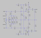
I’m rather confused by several R’s, Y’s and Bl’s that are not connected to each other. What is their meaning, I suspect wires having the colour Red, Yellow and Blue.
If so, where are these wires going to?
Hans
If so, where are these wires going to?
Hans
Last edited:
Those are the wires connected to the board. Yes correct on the colours. Still chasing down all the connections - consider this a work in progress.
I haven't confirmed the resistor values yet - values posted are just from the colour codes. And there may be some mistakes.
Cheers,
Mike
I haven't confirmed the resistor values yet - values posted are just from the colour codes. And there may be some mistakes.
Cheers,
Mike
This is the best I could make of it.
I assumed that both -IN(R) and -IN(L) are connected to GND and not just -IN(R).
Then connected to -IN(L) is a 560R resistor, R20 in my circuit diagram, I very much doubt this value since it would not leave any bias voltage left for the transistors.
The other thing that seems weird is the 8.2nF cap feeding into 82K//33K, giving a pole at 826Hz, a frequency that doesn't seem to make sense.
Hans
Attachments
Will do when I get home next week. I wonder if the reversed phase of one channel of the cartridge has something to do with the circuit weirdness?
I have checked over my circuit "map" and am pretty confident it is correct. The circuit is not symmetrical since one channel input is inverted in phase, and this has to be corrected before the output.
I will measure voltages later this week.
This evening I opened the enclosed metal box under the pcb to find...inductors!

These are 39uH inductors (about 25 ohms DCR). Looks like part of the filter network, that incorporates reverse-RIAA and EQ for the optical cartridge??? Or maybe just RF suppression? I need to run the numbers...
If it is part of the filter network, I'll be able to leave it out in my implementation as I will be using DSP.
Cheers,
Mike
I will measure voltages later this week.
This evening I opened the enclosed metal box under the pcb to find...inductors!
These are 39uH inductors (about 25 ohms DCR). Looks like part of the filter network, that incorporates reverse-RIAA and EQ for the optical cartridge??? Or maybe just RF suppression? I need to run the numbers...
If it is part of the filter network, I'll be able to leave it out in my implementation as I will be using DSP.
Cheers,
Mike
Last edited:
- Home
- Source & Line
- Analogue Source
- DIY optical cartridge preamp