Impressive, Vunce. I always liked Carl's circuit, it has flashes of brilliance and looks a little like JLH thinking.......
HD
HD

Mooly's Mosfet Amp has been on my build list as far back as your nested feedback option was discussed.
I was on a roll and made some more progress this evening.
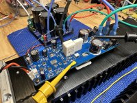
LatFet's installed, boards mounted to heatsinks and powered up just long enough to adjust bias current and confirm offset is still close to 0mV. I won't push my luck further without the off board Thiele network installed.
I was on a roll and made some more progress this evening.
LatFet's installed, boards mounted to heatsinks and powered up just long enough to adjust bias current and confirm offset is still close to 0mV. I won't push my luck further without the off board Thiele network installed.
Attachments
Looking good, Vunce!👍Simultaneous builds here.😁
Powered up Amp#1:
Supply: +/-44V
Opamp pin4: -11V85
Opamp pin6: -4V85
R19/20 junction: 1mV
Temp. T3/T5: 38°C
The temperature was checked with thermocouple attachment for Fluke DMM touching the BJT body.
Amp#2 measured basically the same, no need to repeat.
Next up is mounting the Latfets and inductor winding….

Laterals fitted, mounted on heatsinks, bias adjusted to 100mA and all dc checks still looking excellent. Similarly to Vunce, I've also measured the temperatures of T3 /T5 as around 40deg C. This is with an ambient temperature of 22deg C - positively balmy for this years UK summer so far!
With my currently available transformer (twin secondaries of 20V/1A each), any on-load tests won't particularly exercise the whole setup before hitting the end stops of available power but I'll run some load tests in the morning.


Square wave results at 20KHz and 1KHz with an 8 ohm resistive load. They weren't taken at full output as the 8 ohm load I'd rigged up couldn't handle full power (turned the input signal down when the dummy load started smoking!). All looking good.
I didn't take pics of the sine wave tests but they looked nice and clean across the frequency range 20Hz to 30KHz. Signal source is an HP3312 function generator and the outputs measured with an analogue Hameg scope.
Last edited:
I ran some earlier tests using my BitScope USB digital function generator / scope but the results were pretty noisy. The old Hameg scope and HP kit came into its own for this. As I said in my last post I had the outputs turned up as far as to start clipping but my jury-rigged dummy load started to emit magic smoke. Apart from the smoking load issue, the sin and square wave outputs at full output looked excellent. 👍 👍 👍Those look perfect 👍
Thank you for an excellent design.
I still use an analogue scope, a Hung Chang 100MHz with dual time base (don't ask but I got a really good deal on it new).
There are some squarewave tests here in the thread but these are with the preamp in circuit as well which also has a well defined HF response:
https://www.diyaudio.com/community/...lifier-designed-for-music.119151/post-1545959
There are some squarewave tests here in the thread but these are with the preamp in circuit as well which also has a well defined HF response:
https://www.diyaudio.com/community/...lifier-designed-for-music.119151/post-1545959
If you will have the time, and if you can take the risk,run a clip test,20khz sinusoidal.View attachment 1324063View attachment 1324064View attachment 1324065
Square wave results at 20KHz and 1KHz with an 8 ohm resistive load. They weren't taken at full output as the 8 ohm load I'd rigged up couldn't handle full power (turned the input signal down when the dummy load started smoking!). All looking good.
I didn't take pics of the sine wave tests but they looked nice and clean across the frequency range 20Hz to 30KHz. Signal source is an HP3312 function generator and the outputs measured with an analogue Hameg scope.
I've run the amp clipping (not for long as the load started smoking) with a 20KHz sin wave - no issues found.If you will have the time, and if you can take the risk,run a clip test,20khz sinusoidal.
My Hameg analogue scope and the HP function generator were a great deal for me - I was gifted them by my son when he was updating his own gear. Both items have done a few miles - he brought them back with him when he finished an 18 month stint down in the Antarctic😎I still use an analogue scope, a Hung Chang 100MHz with dual time base (don't ask but I got a really good deal on it new).
^ Nice 🙂 Unless you spend big money a good old analogue scope will winkle out detail and issues that many digital ones can't cope with. Too much quantisation noise.
Chassis packed out and wired up, all systems are go! My Mosfet Amplifier is ready for what it was designed for Music!! 🎶🎶😁
While its cooking (or barely warm) over the weekend I can finish the front panel and wire up the push button switch and LED indicators.
While its cooking (or barely warm) over the weekend I can finish the front panel and wire up the push button switch and LED indicators.
Attachments
Thanks Fellas.
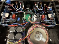
Internal chassis dimensions are: 330mmW x 295mmD x 82mmH
The heatsinks are overkill for this amplifier, run at moderate volume the temperatures are only 8ºC above ambient!
100mA bias current
+/-42V5 supply
5.5uH inductor, parallel resistor is mounted under the pcb (not visible)
I used the board Sadface shared primarily for the purpose of neatly holding the Thiele network, no need for the relay because my softstart and DC protection boards handle that with solid state relays and delay on/instant off.
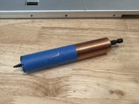
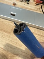
The coils were wound on a homemade jig I made from a piece of 3/4" copper pipe with an old 3/4" Irwin Speedbor wood bit JB welded inside so it can be attached to a cordless drill. A notch was sanded in the edge of the pipe to hold the 16awg wire to start the winding. My wifey controlled the drill as I slow fed the wire to form the coil. The outside diameter of the pipe is closer to 7/8", 60" total wire length.
It's early in the listening stage but everything sounds very good so far, definitely notice this amp has nice bass impact. No hum at all, but have a a bit of higher frequency hiss if my ear is close to the speaker. I don't think I have an ideal match with my current preamp set with 13dB gain, too much overall gain.
Thank you, Mooly, for sharing your creation! 16 years later and still going.....
Geoffw1, your layout was a pleasure to work with, Thank You!
Internal chassis dimensions are: 330mmW x 295mmD x 82mmH
The heatsinks are overkill for this amplifier, run at moderate volume the temperatures are only 8ºC above ambient!
100mA bias current
+/-42V5 supply
5.5uH inductor, parallel resistor is mounted under the pcb (not visible)
I used the board Sadface shared primarily for the purpose of neatly holding the Thiele network, no need for the relay because my softstart and DC protection boards handle that with solid state relays and delay on/instant off.
The coils were wound on a homemade jig I made from a piece of 3/4" copper pipe with an old 3/4" Irwin Speedbor wood bit JB welded inside so it can be attached to a cordless drill. A notch was sanded in the edge of the pipe to hold the 16awg wire to start the winding. My wifey controlled the drill as I slow fed the wire to form the coil. The outside diameter of the pipe is closer to 7/8", 60" total wire length.
It's early in the listening stage but everything sounds very good so far, definitely notice this amp has nice bass impact. No hum at all, but have a a bit of higher frequency hiss if my ear is close to the speaker. I don't think I have an ideal match with my current preamp set with 13dB gain, too much overall gain.
Thank you, Mooly, for sharing your creation! 16 years later and still going.....
Geoffw1, your layout was a pleasure to work with, Thank You!
Attachments
Last edited:
Thanks for the kind words 🙂
Any preamp need only have minimal voltage gain if at all (well at least x1 of course). I used this which is set here for 25kHz squarewave. Rin is nominally 18k on CD input but each other input (DAB Minidisc, Aux etc) has the value adjusted to give equal subjective values between the different sources. Rin and the FET's are duplicated for each input and feed into the virtual earth mixer:

Any preamp need only have minimal voltage gain if at all (well at least x1 of course). I used this which is set here for 25kHz squarewave. Rin is nominally 18k on CD input but each other input (DAB Minidisc, Aux etc) has the value adjusted to give equal subjective values between the different sources. Rin and the FET's are duplicated for each input and feed into the virtual earth mixer:
Attachments
Pleased you liked it. I try to think about both the initial build and servicing when doing any layout.Geoffw1, your layout was a pleasure to work with, Thank You!
This looks great! Where did you get your speaker protection boards from?Chassis packed out and wired up, all systems are go! My Mosfet Amplifier is ready for what it was designed for Music!! 🎶🎶😁
While its cooking (or barely warm) over the weekend I can finish the front panel and wire up the push button switch and LED indicators.
No hum at all, but have a a bit of higher frequency hiss if my ear is close to the speaker. I don't think I have an ideal match with my current preamp set with 13dB gain, too much overall gain.
Lowered preamp gain and speakers are silent now, no more hiss.

The chassis size eliminated the option of building a dual mono power supply and I was a bit concerned this build wouldn't be hum free using a shared power supply. Boy was I wrong, it's probably one of the quietest amps in my stable!
This looks great! Where did you get your speaker protection boards from?
ready-to-run-rtr-ssr-dc-speaker-protection-and-delay-gb.340694
- Home
- Amplifiers
- Solid State
- My MOSFET amplifier designed for music